Kogan Smart Plug: No Esp8266? (Tuya WB2S)
Changes
2021-05-27 V1.0 started
2022-05-30 V1.1 notes about ESP02S
2022-09-29 V1.2 notes about potentially using OpenBeken
2024-06-25 V2.0 added a table with the pinouts/connections… yes my sketch was a bit confusing
Summary
UPDATE Sep 2022: OpenBeken is an option to flash these, my openbeken notes went out of date pretty quickly, as it is a lot easier to use now, but here are my notes about setting up OpenBeken https://zorruno.com/2022/zemismart-ks-811-with-openbk7231n-openbeken/
UPDATE May 2022: It looks like there is a direct WB2S replacement module, the ESP-02S
https://templates.blakadder.com/ESP-02S.html
https://www.aliexpress.com/item/1005003690674591.html
It is getting more and more common to get smart devices that have chips other than ESP8266 in them, and these chips are usually not flashable with the likes of Tasmota, ESPHome etc.
Many of these used to have ESP8266 processors/modules, so if you bought one later you are a bit stuffed if, like myself you prefer not to use cloud connected services such as Tuya for your home automation.
A sensible way to solve it, but one that requires a bit of work is to hardware replace the chip module. This is doable provided:
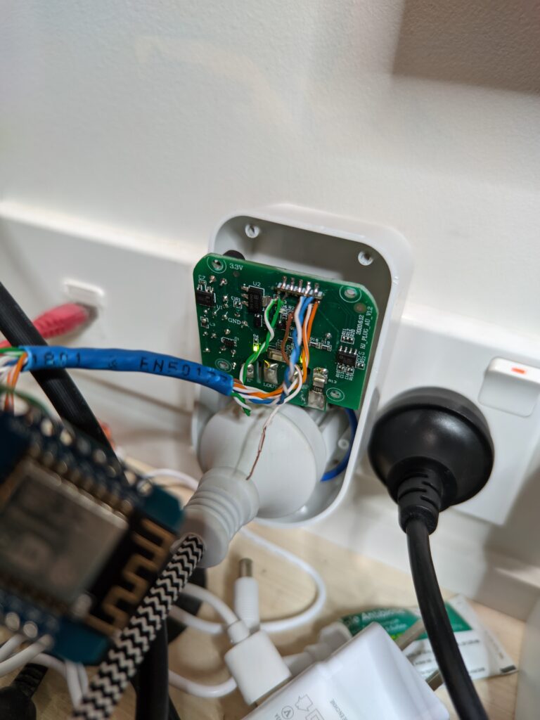
- You have enough room in the device to swap swap it out, especially if the old module is a bit smaller, as with this device below (and I guarantee this device is generic enough that there will be other badged products almost identical)
- It isn’t a surface mount device, directly soldered to the main board (good luck with that)
- The device is easy enough to pull apart and access the board (some lightbulbs etc can be a bit fiddly)
I highly recommend you buy products like Athom (which are preflashed with Tasmota, ESPHome and others), or Sonoff and Zemismart (which aren’t too hard to flash yourself). That will save you a lot of hassle. Sometimes though… you find other products that are just soooo cheap, you have to try them out!
I have also managed to flash a few Arlec bulbs with Tasmota, (not sure if they still have ESP8266s) and have swapped out a WB3S chip on a smart LED controller (Powertech, from Jaycar). Which initially came with ESP8266 chips, and I’ve flashed them in the past with no hardware mods.
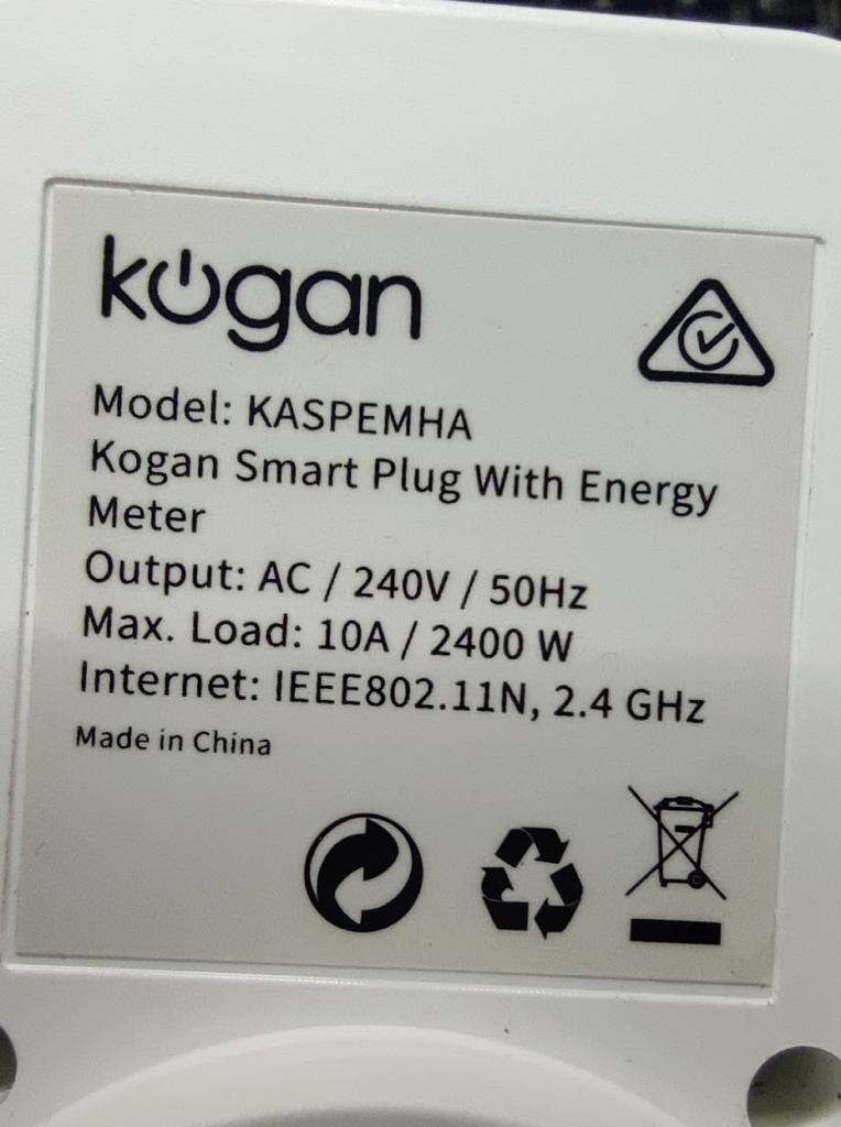
Kogan Model
- Model KASPEMHA
- Kogan Smart Plug with Energy Monitor
- 10A Max Load
- Link: https://www.kogan.com/nz/buy/kogan-smarterhome-smart-plug-with-energy-meter-pack-of-4-kogan/
- Bought for about NZ$50 for 4 units. As of writing this, the 4 packs were already sold out.
To be honest, most of the power monitoring I do is built in, either at the DB or in the device. I am not really a fan of the plug in monitors as it annoys me when they get switched off, and they visibly take up a power socket. However, I had a couple of dishwashers to monitor, and these were perfect.
Internals
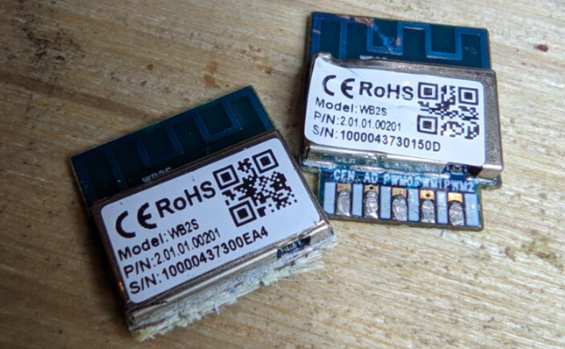
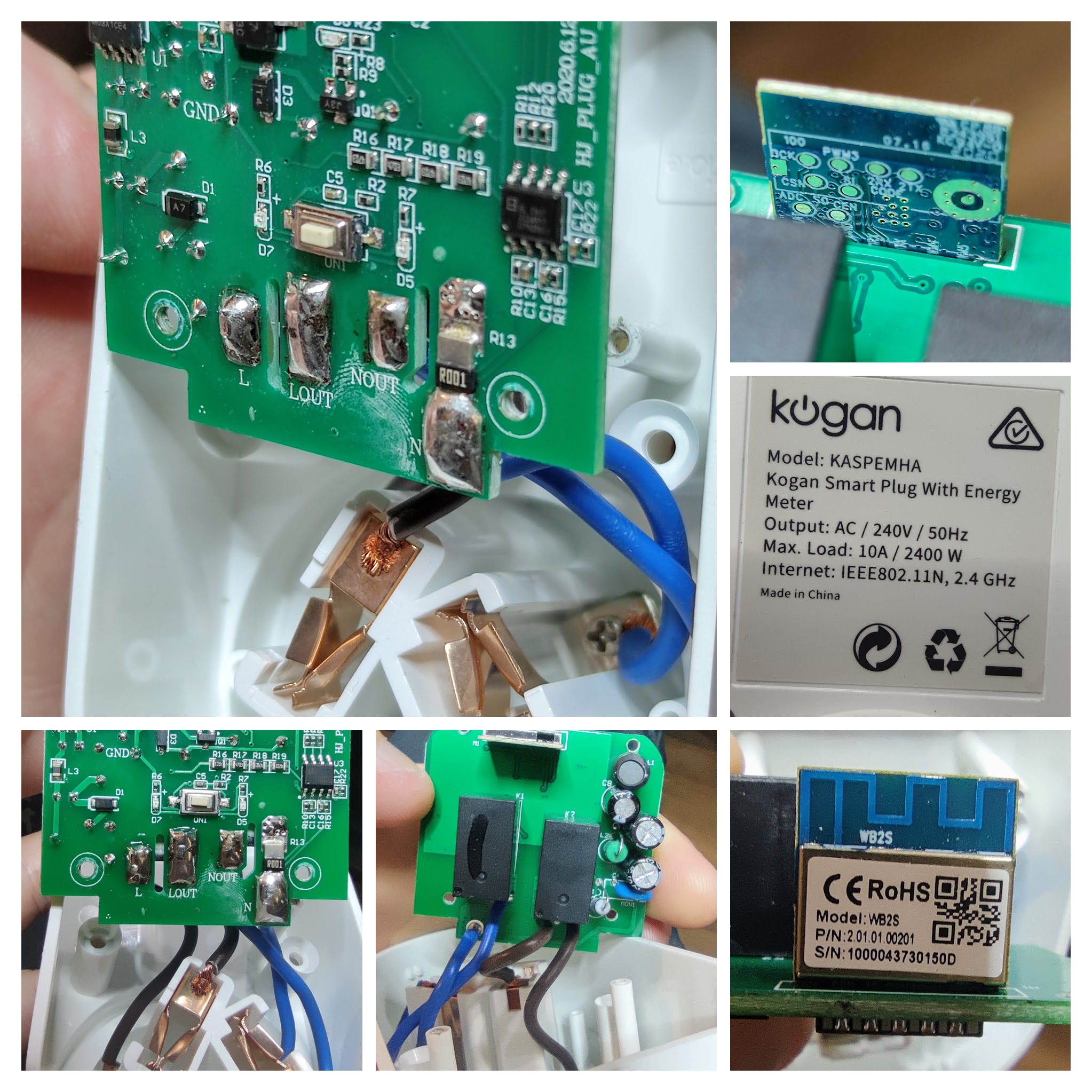
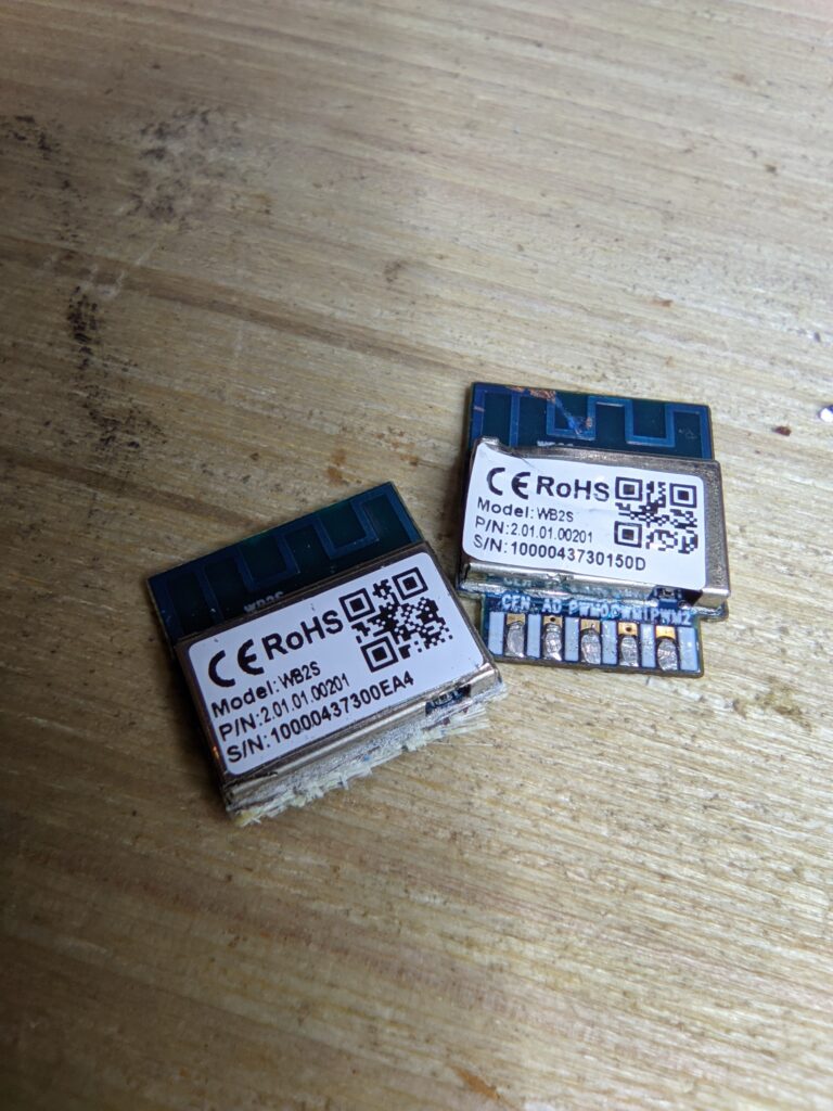
Unfortunately as soon as I opened it I found it had a WB2S chip in it, not the ESP8266/8285 or equivalent. It runs Tuya, and just for fun I did play with Tuya Local for a bit, but there is no known way to flash this with something like Tasmota at this stage.
There is a fair bit of room in the housing, so I knew it shouldn’t be hard to swap the daughterboard for an ESP12F or similar.
WB2S Pinout
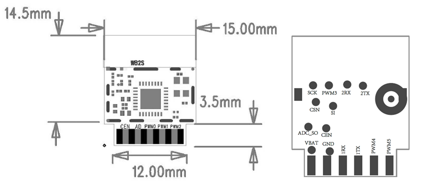
Not much to these WB2Ss really.
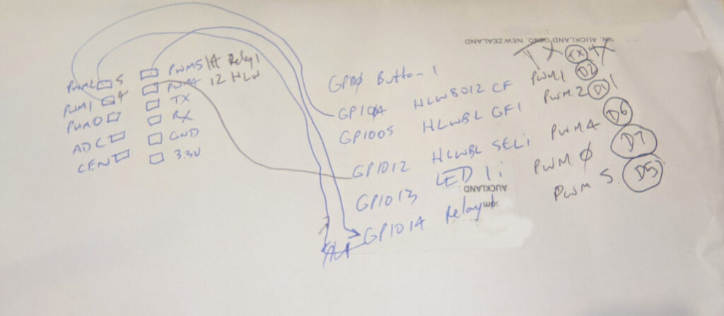
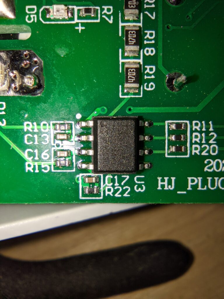
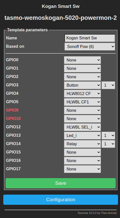
I next had to find out what setup the smart plug used for power monitoring. A good look at the board found what looked to be a HLW8012 power monitoring chip, similar to what is used on the Sonoff Pow R2, which needs three I/O pins. One for a pulsed output to the micro giving active power, and one for current/voltage… and a 3rd pin is the output from the micro to select whether you are reading either current or voltage on the output (you can’t do both at the same time).
I used this to help trace the I/O I’d need on the ESP8266, and match it to the I/O in Tasmota that the Sonoff Pow R2 would use.
I used Tasmota for this project, but if you are using ESPHome, there is info on the HLW802 here: https://esphome.io/components/sensor/hlw8012.html
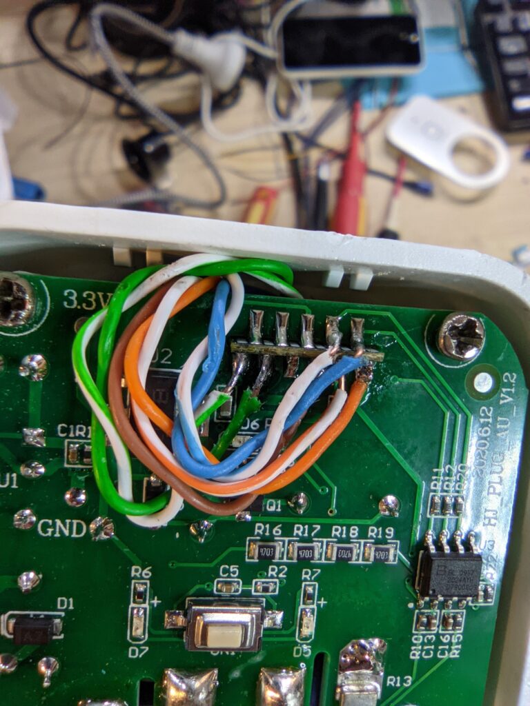
I sketched out a diagram of what I’d need to connect where, and it looked like this on the back of an envelope… obviously some bits are missing on the sketch, so see the table below of final connections. Note I didn’t bother connecting up the LED… I didn’t need a visual status.
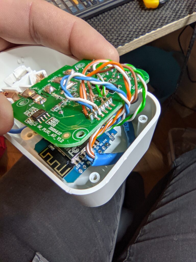
| WB2S | D1 Mini | Wire Colour | Function (Tasmota) |
|---|---|---|---|
| PWM2 | D1 (GPIO5) | Blue | HLWBL CF1 |
| PWM1 | D2 (GPIO4) | Blue/White | HLW8012 CF |
| PWM0 | D7 (GPIO13) | LED_i (NOT USED, left unconnected) | |
| A0 | |||
| CEN | |||
| VBAT | 3V3 | Orange | +ve 3.3V |
| GND | GND | Orange/White | GND |
| RX | TX (GPIO1) | NOT USED | |
| TX | RX (GPIO3) | Brown | Button1 |
| PWM4 | D6 (GPIO12) | Green | HLWBL SEL_i |
| PWM5 | D5 (GPIO14) | Green/White | Relay1 |
D1 Mini Pro replacement
My method of replacing this was pretty crude and was intended to be a proof of concept before I replaced one permanently.
I had a bunch of D1 mini pro boards, and because there was plenty of space in there that is what I went with. You are probably unlikely to get away with that with other devices, and will need at least an ESP12F or similar (which is what I have used since, for other devices)
As is more often usual though… once it worked I left it as is! It all fitted nicely back in the enclosure. Later chip replacements I did were a lot tidier.
Calibration
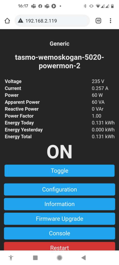
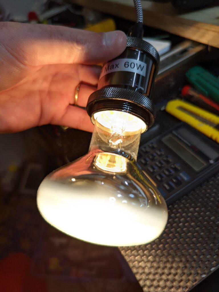
This unit does power monitoring, and it definitely needed calibration. The HLW802 outputs a frequency for power, so you want to set the value correctly (it was way off). My favourite way to do this is with a Tungsten filament bulb or two, that have a known wattage (these are usually pretty accurate) and I have a couple set aside for this purpose.
Follow the power calibration instructions on the Tasmota site, using the offset valu with the PowerCal command, eg:
PowerCal 10000Related projects of mine
WB3S replacement for Home Automation devices (with an ESP12F)
https://zorruno.com/2022/wb3s-replacement-for-home-automation-devices/
Flashing an Arlec ‘grid connect’ lightbulb
https://zorruno.com/2020/tasmota-flash-of-gld110ha-smart-globe/
Power monitoring, completion notification and logging (Various power monitoring methods)
https://zorruno.com/2021/nodered-appliance-completion-notification/
ESPHome PEM-004T Power Monitoring (Oven reminders with Node Red)
https://zorruno.com/2022/nodered-oven-notifications/
Replacement Chip Options
UPDATE May 2022: Refer first paragraph for the most sensible replacement, the ESP-02S.
There are similar style boards in a zigbee module too. I bought a few for other purposes, but there is probably something that slots right in with the correct i/o (let me know if you find something).
The zigbee modules I bought only have a single input and one output, so only useful for simple smart switches: https://www.aliexpress.com/item/1005003295743076.html
Other relevant links
Using Tuya Local
https://zorruno.com/2021/kogan-smart-plug-and-tuya-local-notes/
Using OpenBeken (on a different device)
https://zorruno.com/2022/zemismart-ks-811-with-openbk7231n-openbeken/
Tuya’s datasheet for the WB2S
https://developer.tuya.com/en/docs/iot/wb2s-module-datasheet?id=K9ghecl7kc479
A dimmer with the same chip
https://community.home-assistant.io/t/unkown-tuya-chip/153591/55
More swaps by blackadder
https://blakadder.com/frankenstein-saturday-3/




hello,
It seems there is error on your sketch diagram, button is on RX and not TX, isn’t it ?
At the end how many wires have you soldered 6 or 7 because on one of your picture there is a brown and white wire conected on R2 what is it ?
Thanks
Sorry – yes the sketch was a bit confusing! It was a while since I put this together, and the plug has since been pulled apart but I have now added a table which I’m relatively sure is the correct connections/wire colours I used there. I didn’t bother connecting the LED but the brown should be the button (and 6 other wires as per the table). If you do something similar, let me know if i’m incorrect…
hello,
thanks for answer.
i had other question, I have connected WB2S Tx pin to wemos d1 mini Rx pin like is it describe on your board.
But when I click the button on the plug nothing happens.
Normally we should be able to put the plug ON or OFF manually isn’it?