Zemismart KS-811 with OpenBK7231N/OpenBeken
Summary
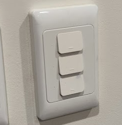
I have bought a number (at least 50) Zemismart wall switches in the past, as they come in 1, 2 and 3 buttons, have the NZ/AU style design & box size and have an ESP8266 for the use of Tasmota or espHome. Recently a friend bought some of them, but they now have a Tuya style microprocessor, the BK7231N. I’m not sure at this stage if it is all Zemismart switches as the ones he bought are the “No Neutral” capable versions and I have always used a different model from their catalogue.
Generally, and more recently I’d just desolder the daughter board with something like a WB3S, and replace it with an ESP12F or similar (See my notes here, and here), but there is now another option for firmware replacement.
UPDATE 1: I ordered some more of the original model and yes… they now also use the BK7231N. The last order I made that had ESP8266 boards was Oct 19, 2020.
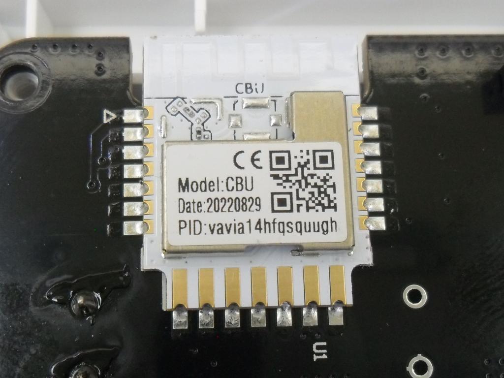
UPDATE 2: A friend ordered some of the KS-811-2 (2 button versions) and it appears they were a slightly older board. They did NOT have the BK7231N chip soldered directly to the board, but did have a CBU-IPEX Module as a daughterboard (which has a BK7231N on it). See below for what was needed to flash this version. Spoiler alert… some deconstruction work is needed.
The below will summarise how to flash OpenBeken to a KS-811-3 with this particular BK micro. It assumes you are familiar with IoT device flashing with an FTDI, soldering, Linux (probably), and can figure out how to take out the 4 screws to remove the backbox of the Zemismart unit. Note that all links to products etc here are just ones I have used, there is no guarantee they will work for you or be the best supplier.
OpenBK7231T/OpenBeken
OpenBK7231T/OpenBeken is a Tasmota/Esphome replacement for new Tuya modules featuring MQTT and Home Assistant compatibility. IT actually supports BK7231T (WB3S, WB2S, WB2L, etc), BK7231N (CB2S, CB2L, WB2L_M1, etc), T34 (T34 is based on BK7231N), XR809 (XR3, etc), BL602 and W800 (W800-C400, WinnerMicro WiFi & Bluetooth), W801
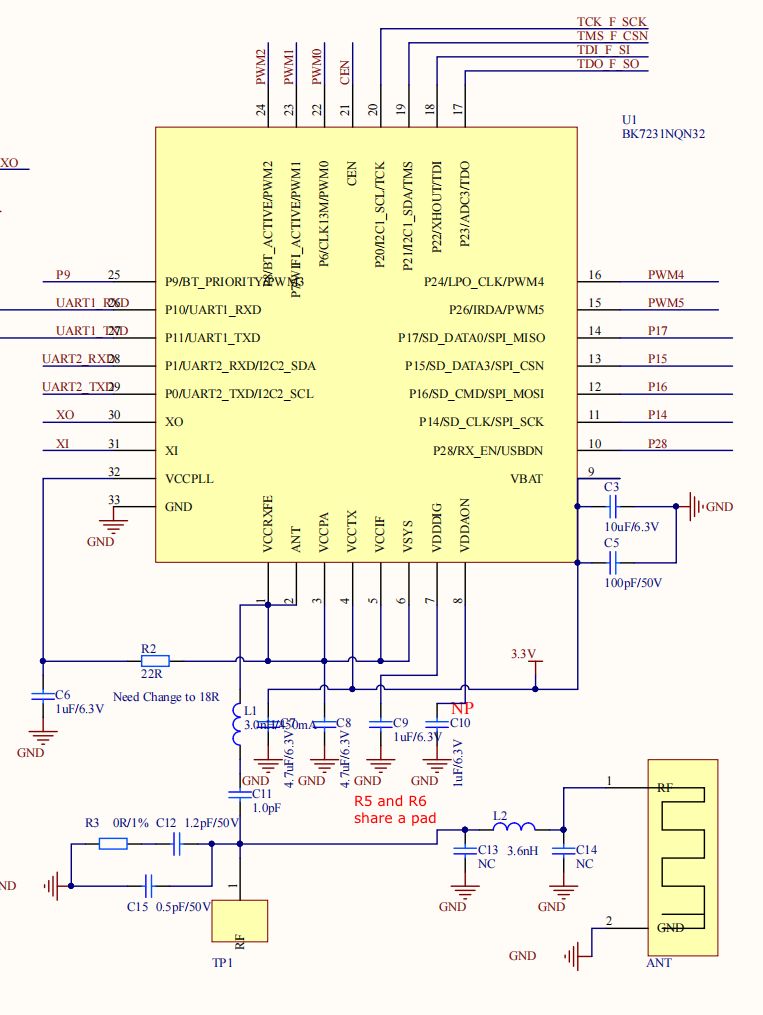
The processor in the KS-811 is the BK7231N. I can’t find a very good pinout diagram (there are a bunch of similar processors around, eg this is close, but not the exact same pin layout), but this schematic below seems to be the one. This page, detailing a Tuya Wi-Fi & Bluetooth LE SoC NANO (with BK7231N) also shows more detail and the PIN names/purpose in a list.
Install Process
We with use the UART serial bootloader method, and need obtain the python uartprogram from the project libraries. This has been specifically modified for this purpose by the project author from the Beken programming libraries.
I’ll assume you are using Linux. If on Windows or Apple, have a look at the OpenBeken instructions. For Windows there is a flashing tool called BKwriter, although it doesn’t work for all chips at this stage apparently. You will also need a USB to TTL converter with 3.3V logic levels (FTDI), and some hook up wire/soldering skills etc to flash the micro.
Head to https://github.com/OpenBekenIOT/hid_download_py for more info.
You’ll first need git and python installed, and then grab the repo with
git clone https://github.com/OpenBekenIOT/hid_download_py.git You’ll also need the following if you haven’t got them already
$ apt install python3-hid python3-serial python3-tqdmgo to the location of the download & run
$ python3 setup.py install --userThe uartprogram will now be installed. Next grab the actual Binary we will need to flash. They are precompiled for the various chips here (no need to compile your own, but you can)
https://github.com/openshwprojects/OpenBK7231T_App/releases
For this chip, you want the UART Flash or the OpenBK7231N_QIO_x.xx.xx.bin version (with the QIO in it). Note you should check for the latest version number… don’t just use the link I have put here.
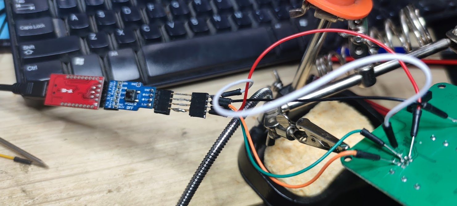
$ wget https://github.com/openshwprojects/OpenBK7231T_App/releases/download/1.12.61/OpenBK7231N_QIO_1.12.61.bin Connect up your FTDI to the micro, and ensure the “I” pin is grounded thoughout the flash process (from first power up). See below for serial connections and photos.
You need to know which serial port your FTDI is connected to. In Linux, you can run the below and it will give you that info.
$ sudo dmesg | grep -i FTDI

usb 1-1.1: FTDI USB Serial Device converter now attached to ttyUSB0
In the location where the download flash .bin is located, run the following (I’m using USB0 for serial). This chip needs the unprotect and the startaddr to flash correctly (others may not). Also see below re issues I found with baud rate, FTDI and WriteSector failures.
$ python uartprogram OpenBK7231N_QIO_1.12.61.bin --unprotect -d /dev/ttyUSB0 -w --startaddr 0x0

UartDownloader....
programm....
Write Successful: |##################################################|[ 15.1k/s]
That is it, you have the new firmware installed, and you can follow the OpenBeken configuration instructions.
KS-811 connections for FTDI
Flashing Notes:
- Only use 3.3V
- The I pin has to be pulled low (GND) throughout the entire flash process
- Rx (Receive) on the board goes to Tx (Transmit) on the FTDI (and vice versa)
- If you have issues with errors, check/replace your USB cable, your FTDI (some FTDI chips apparently have issues), play with the baud rate (faster or slower), make sure there is enough power from your USB port.
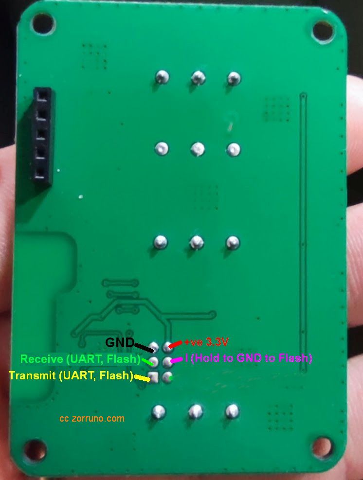
KS-811 Connections
The easiest connections are on the back of the KS-811-3 (3 button) Zemismart light switch. There is no need to remove the front switch mechanisms (although I have in the photos). Obviously just ensure you are NOT using mains to power anything… ie disconnect it from the back box, it is easy to just remove the back from the front with 4 screws.

KS-811-2 with IBEX-CBU
Credit goes to PMB for working on this section and providing the photos below. Refer to the photos to help with this flashing guide.
The KS-811-2 (2 button version of the switch) had a CBU module onboard, rather than the chip directly on the main board. It isn’t known if this is a temporary design by Zemismart… all of them (3,2 and 1 button versions) may have the BK chip direct soldered now.
Unfortunately with this CBU module, you won’t be able to get to the “Mode Selection Pin” or CSN, (which is marked “I” on the other boards). This pin is underneath the module and not bought out to the side of the board and you need to set this low in order to flash. There is no easy way to get to it so the sensible way to flash this is:
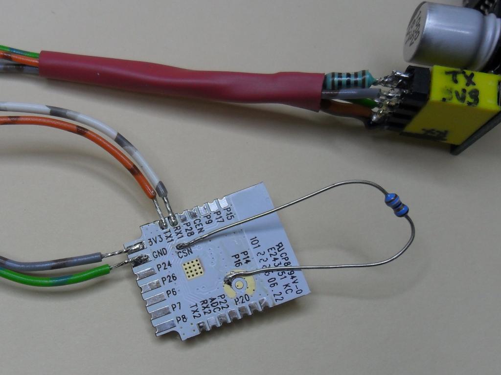
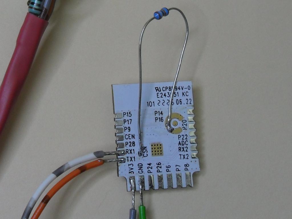
- Desolder the whole CBU module. Use a reflow gun or if you think you can, a soldering iron and wick/desolder gun etc. There is plenty of helpful info online to show you some tips for this.
- The module has all the pins nicely labelled. Connect to the FTDI as per the photos below. (In these photos, a resistor is use used to ground the CSN pin to an unused aerial ground point, but that isn’t necessary (it was just convenient). Be careful, you can easily overheat and lift this pad.
- Flash the chip as per the above for the 3 button version.
- Resolder and set up OpenBeken.
This is a link to the CBU module datasheet. Some research was done to see if there was a similarly pinned module that would replace the CBU module (and had an ESP8266), but nothing suitable was found (the ESP12-F is not suitable, with different pinout and pitch).
Photos of the KS-811-2, CBU Module and Flashing


Helpful Links
- Main Project Link on Github https://github.com/openshwprojects/OpenBK7231T_App
- A useful guide to install of OpenBK7231T on an Australian DETA 6922HA Series 2 Double Power Wall outlet. (It uses WB3S) https://community.home-assistant.io/t/detailed-guide-on-how-to-flash-the-new-tuya-beken-chips-with-openbk7231t/437276
- A useful Video howTo for Flashing TUYA CB3S BK7231N with Openbeken on a generic Tuya touch wallswitch. (CB3S Micro). https://www.youtube.com/watch?v=dZukpyLeDHo
- A teardown of a product with a CB2S Module (there are lots of teardowns here with that chip) https://www.elektroda.com/rtvforum/topic3874289.html
Flashing Commands and Issues I Found
$ python uartprogram ../tuya-iotos-embeded-sdk-wifi-ble-bk7231n/apps/tuya_demo_template/output/1.12.63/tuya_demo_template_QIO_1.12.63.bin -d /dev/ttyUSB0 -b 115200 -w

UartDownloader....
programm....
Cannot get bus. : |
Cannot get Bus. Well, this to me meant that I hadn’t grounded the “I” pin. I needed to have this held to ground from boot up for the entire flashing period (unlike an esp8266, in which you just pull to ground on boot) . It could also mean you have the wrong serial port, or your RX/TX are swapped.
$ python uartprogram ../tuya-iotos-embeded-sdk-wifi-ble-bk7231n/apps/tuya_demo_template/output/1.12.63/tuya_demo_template_QIO_1.12.63.bin -d /dev/ttyUSB0 -w

UartDownloader....
programm....
Gotten Bus...   : |                                                  |[    ?k/s]caution: ignoring unexpected reply in SetBaudRate
WriteSector 1 Failed: |#######################################       |[ 18.3k/s]
“ignoring unexpected reply in SetBaudRate” could have been part of the issue I found later. You’ll see above that I used -b 115200 to change the baud rate, but didn’t need to on final successful flash (this is a suggested way to solve the WriteSector error).
$ python uartprogram OpenBK7231N_QIO_1.12.61.bin --unprotect -d /dev/ttyUSB0 -w --startaddr 0x0

UartDownloader....
programm....
Write Successful: |##################################################|[ 15.1k/s]
Finally a successful flash. After changing as many things as possible (cables, USB Ports, my chair), I ended up using a different FTDI and that solved it. My first FDDI uses a CN480661 Chip. This did not work (not sure why). The one that worked for me uses the older CH340G (16 Pin) Chip.
KS-811 Specific Configuration
Once powered up and rebooted, you need to follow the OpenBeken App wiki, which is here
https://github.com/openshwprojects/OpenBK7231T_App/wiki/Wiki-Home
Like Tasmota, the device will present an open Wireless AP which you should connect to (we with a phone) and supply your actual Wifi credentials.
Then you go in and set your MQTT server, and set the PIN roles (at time of writing, there are a number of preset devices you can select from, but not the KS-811 devices. I have submitted a patch to github for this switch)
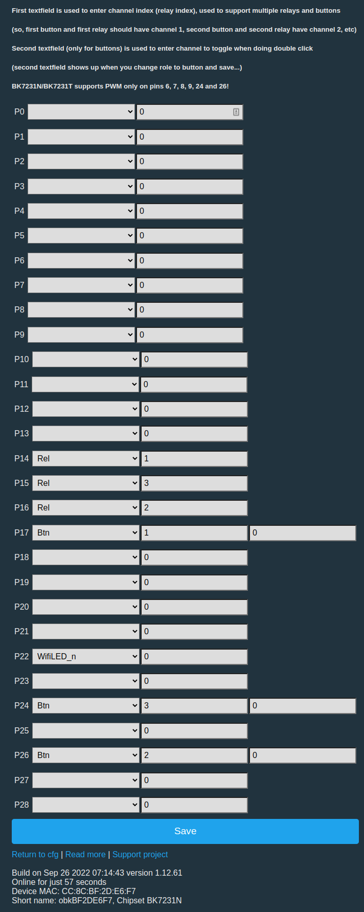
KS-811-3 Pin Roles
Pin Roles are defined here (you can likely just leave some out for the 1 and 2 button versions of the switch, but I haven’t tried this)
https://github.com/openshwprojects/OpenBK7231T_App/wiki/Pin-Roles
After a small amount of circuit tracing (and locating the correct chip datasheet), this is what I came up with that seemed to work.
- The LEDs and relays are wired in parallel, you can’t control one without the other.
P14, P16 and P15, are the Relays/LEDs in that order. “Rel” Pin Role, with 1, 2 and 3. - The buttons, from top down are P17, P26, and P24. “Btn” Pin Role, with 1, 2 and 3.
- The LEDs are dual colour when the relay operates (red or blue) and there is also a separate GPIO pin that will turn them off/on (Pin P22) – this is the same as the previous ESP8266 model (as can be seen from the Blakadder template) You could use another GPIO role to turn the blue LEDs off (eg at night) and I was doing this with mine in bedrooms. For the below setup, I opted to use “WifiLED_n” as the pin role, and this means when wifi is being obtained, the LEDs will flash, but with steady Wifi they will be Blue (or Red when the relay is on)
What next?
MQTT Use
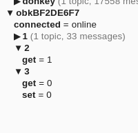
If you want to use it with MQTT, this is what the sub/pub looks like. It is pretty simple, and all you have to do is set the MQTT setting in the appropriate menu.
You set on okb123456AB/1/set (using the ID of the device, the number 1 for first relay and a 0 or 1 to turn it on or off. You can read the status on the ‘get’ topic. There is also a “connected” topic for online/offline.
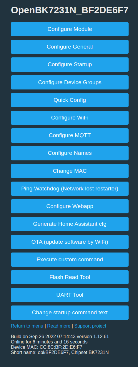
Like Tasmota, on the main Web page there are buttons to turn the three relays on and off.
Home Assistant Use
There is also a button to generate a home assistant configuration. It just produces the correct MQTT notation, no “auto setup” or other API. In my case it looks like this, and I pasted it in my HA configuration files.
mqtt:
  switch:
  - unique_id: "OpenBK7231N_BF2DE6F7_relay_0"
    name: "obkBF2DE6F7 0"
    state_topic: "obkBF2DE6F7/0/get"
    command_topic: "obkBF2DE6F7/0/set"
    qos: 1
    payload_on: 1
    payload_off: 0
    retain: true
    availability:
      - topic: "obkBF2DE6F7/connected"
  - unique_id: "OpenBK7231N_BF2DE6F7_relay_1"
    name: "obkBF2DE6F7 1"
    state_topic: "obkBF2DE6F7/1/get"
    command_topic: "obkBF2DE6F7/1/set"
    qos: 1
    payload_on: 1
    payload_off: 0
    retain: true
    availability:
      - topic: "obkBF2DE6F7/connected"
  - unique_id: "OpenBK7231N_BF2DE6F7_relay_2"
    name: "obkBF2DE6F7 2"
    state_topic: "obkBF2DE6F7/2/get"
    command_topic: "obkBF2DE6F7/2/set"
    qos: 1
    payload_on: 1
    payload_off: 0
    retain: true
    availability:
      - topic: "obkBF2DE6F7/connected"
  - unique_id: "OpenBK7231N_BF2DE6F7_relay_3"
    name: "obkBF2DE6F7 3"
    state_topic: "obkBF2DE6F7/3/get"
    command_topic: "obkBF2DE6F7/3/set"
    qos: 1
    payload_on: 1
    payload_off: 0
    retain: true
    availability:
      - topic: "obkBF2DE6F7/connected"
Other OpenBeken Setup
This is only a simple example, with 4 buttons, 4 relays and LEDs that mimic the states. OpenBeken can handle a bunch of other sensors, much of the Tasmota scripting code and more complex devices.


Thanks to your instructions I’ve managed to flash both a KS-811-3 and a couple of KS-811-1 Single Button switches and it was super easy.
I played a game of guess on the single switch config and found the following…
16 – Rel – 1
22- WifiLED_N – 0
24 – Btn – 1
cheers Tim