Vehicle 12V Battery Monitoring with ESP8266 and ESPHome
Changes
2022-10-19 V1.1 Addition of some graphs showing voltage measurements
2023-05-27 V1.2 Minor changes to the ESPHome yaml & notes… (I built a second one for another vehicle)
2024-05-20 V1.3 Further updates, comments and tidyup of the ESPHome yaml
2024-05-20 V1.4 minor change to deep sleep method in yaml
2024-06-30 V1.5 hmm sorry, error in my recent deep sleep YAML update (no wonder my units weren’t waking…). Also other yaml and page tidyups.
2024-07-01 V1.6 a note about adding iBeacon tracking
Summary
Using the analogue input on an ESP8266 and a voltage divider to monitor the status of and report on a 12V battery in a car.
Features
- A calibrated measure of the battery, which could be up to 15Vdc
- Sending regular reports to MQTT (say, every 10 mins)
- Use low power (and deep sleep mode where possible) to avoid draining the battery further
- Easy removal/install
- A decent Wifi Range
Method
I have a Nissan Leaf, and they seem poorly designed to keep the 12V battery topped up. They charge when the car is charging (i.e. the drive battery is on charge) and also when you are actually moving. Obviously this should be better than ICE vehicles, as they also only when the engine is on.
Leaf 12V batteries seem to quite commonly be the cause of issues, and especially when they have been sitting unused for a while. It is sad really that they have to keep the HV and 12V system completely separated, as there are times when the 12V battery (around 1kWh of storage) can go flat even though the car main drive battery (24kWh) is full. This is no doubt similar to other EVs though, and maybe newer cars just charge the 12V quicker when charging is possible.
X and G models of leaf have a small solar panel <5W on the rear spoiler which may help, but it is only a tiny amount of current, so who knows (mine doesn’t have one).
I did experiment with changing the 12V battery to a Lithium setup (documented separately), but in the mean time I wanted a way to monitor the battery Voltage, and my home automation could notify me if it drops too low.
Using this simple setup below, I can get an accurate reading and a graph of voltage, but ONLY if the car is at home and in WiFi range. Normally I’d put potential improvements at the bottom of my project info, but I’ll list them here and maybe will try and tick some off in the future.
This project is obviously useful for any vehicle, EV or not.
Hardware
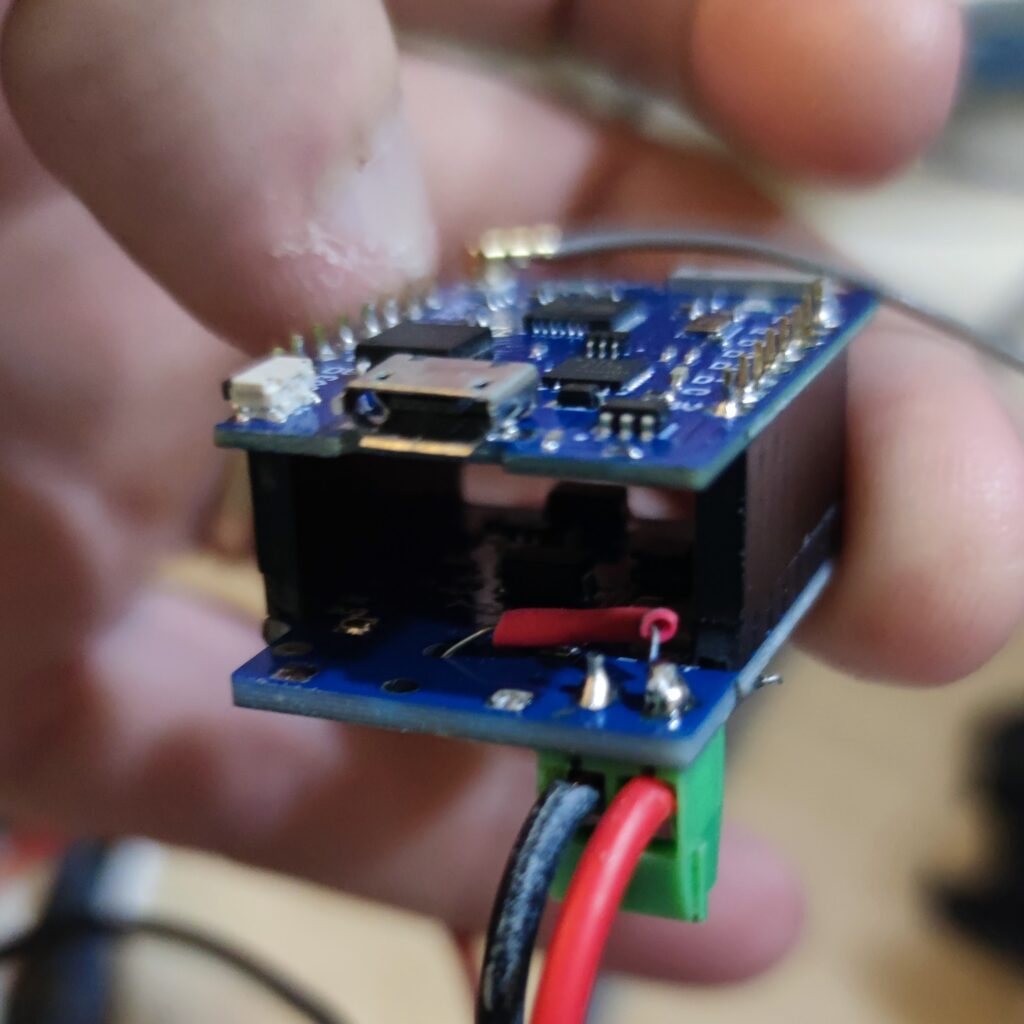
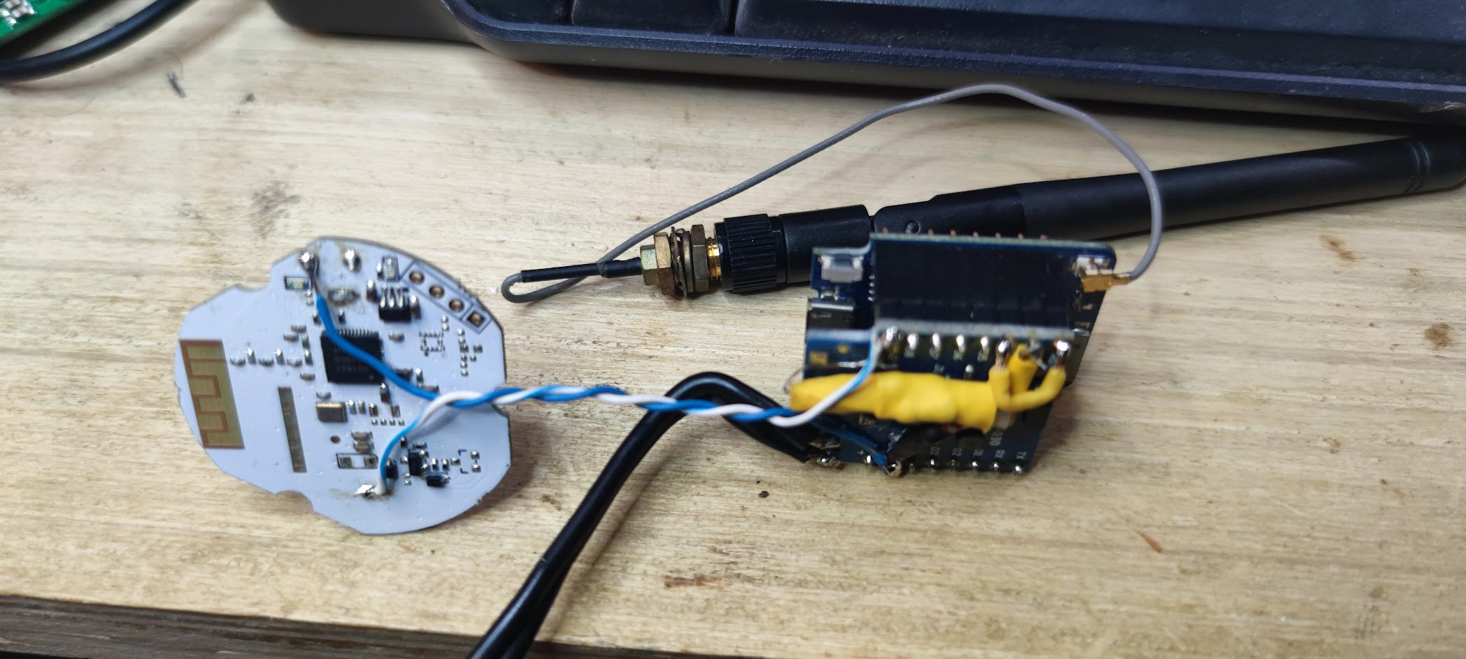
I used a Wemos D1 Mini Pro (or a clone of it..) and an off the shelf ‘power shield’ to power it from the 12V. I wanted the Pro due to the aerial connector (don’t forget to move the 0 Ohm resistor bridge to be able to use the attached aerial). Note that some of my D1 Minis wouldn’t even get a wifi signal without the external aerial, I suspect due to the switching of the power supply components on the power shield.
I just used some leads with crocodile clips for the power so I could just clip it on my battery (and to a close grounded bolt) and it could be removed when no longer needed. You’ll see I used a couple of resistors in parallel… as that is what I had sitting around.

Voltage Divider
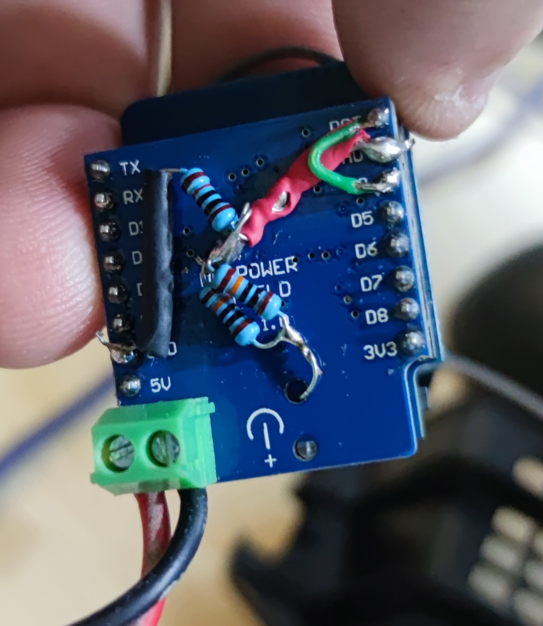
On the back of the power shield, I soldered up some resistors in a voltage divider arrangement, and connected it up to the 12V input (you can see in a photo that I went though the hole in the power board). You can buy a ‘voltage divider’ sensor, but a couple of resistors (plus some screw terminals) is all that is on it. I connected the divider from the +ve and GND inputs to the Analog input pin on the ESP8266.
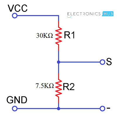
Something in the order of 30k Ohms and 7.5k Ohms would be about right, but I just used what I had that was close (you can calibrate the input later) – not pretty as I added a couple to tweak the overall values.
These values should get you a safe range from 0-16V. The ESP requires maximum of 1V on its A input, but the Wemos has another voltage divider to get the required 1V from its 3.3V supply range (so the max allowed to the Wemos Analogue pin is 3.3V)
A voltage divider with 30k and 7.5k would give you 3.3V on the Wemos input, from about 16.5V input which should be fine.
Deep Sleep Hardware
In order to get deep sleep capability, you also need to connect the “Wake” pin (GPIO16 or D0 on the D1 Mini I used) with the “Reset Pin” RST. You can see this loop of green wire on my board. That’s all you need to do hardware-wise.
I suggest you do ALL your custom wiring on a daughter board of some sort, such as the D1 Mini Power shield. This includes the link for the reset pin, power connection and all bridge resistors. That way, if the D1 Mini Board fails (cars are harsh environments), you can just swap it out. I’ve already had one D1 mini failure…
Nissan Leaf Installation
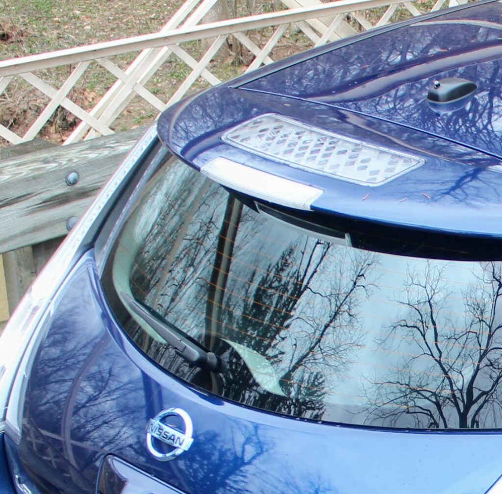
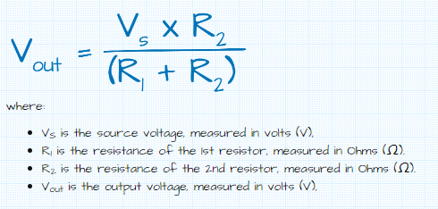
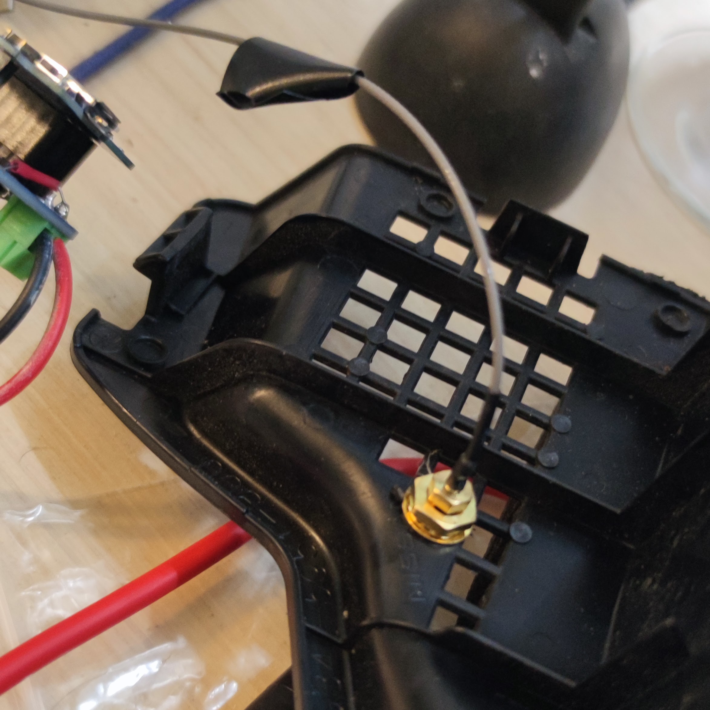
I wrapped the board in some wide heatshrink and some tape to make it relatively water resistant, and mounted it in the front left cowl area in front of the windscreen. This is nice and close to the battery and there is a lift out piece of plastic above the shock tower mounts (I got some shock tower covers at the same time, as this is a common place that you get rust in a leaf).
I also wanted to be sure the aerial wasn’t hidden away under metal, as it wasn’t that close to my nearest WiFi access point when parked in its usual spot outside.
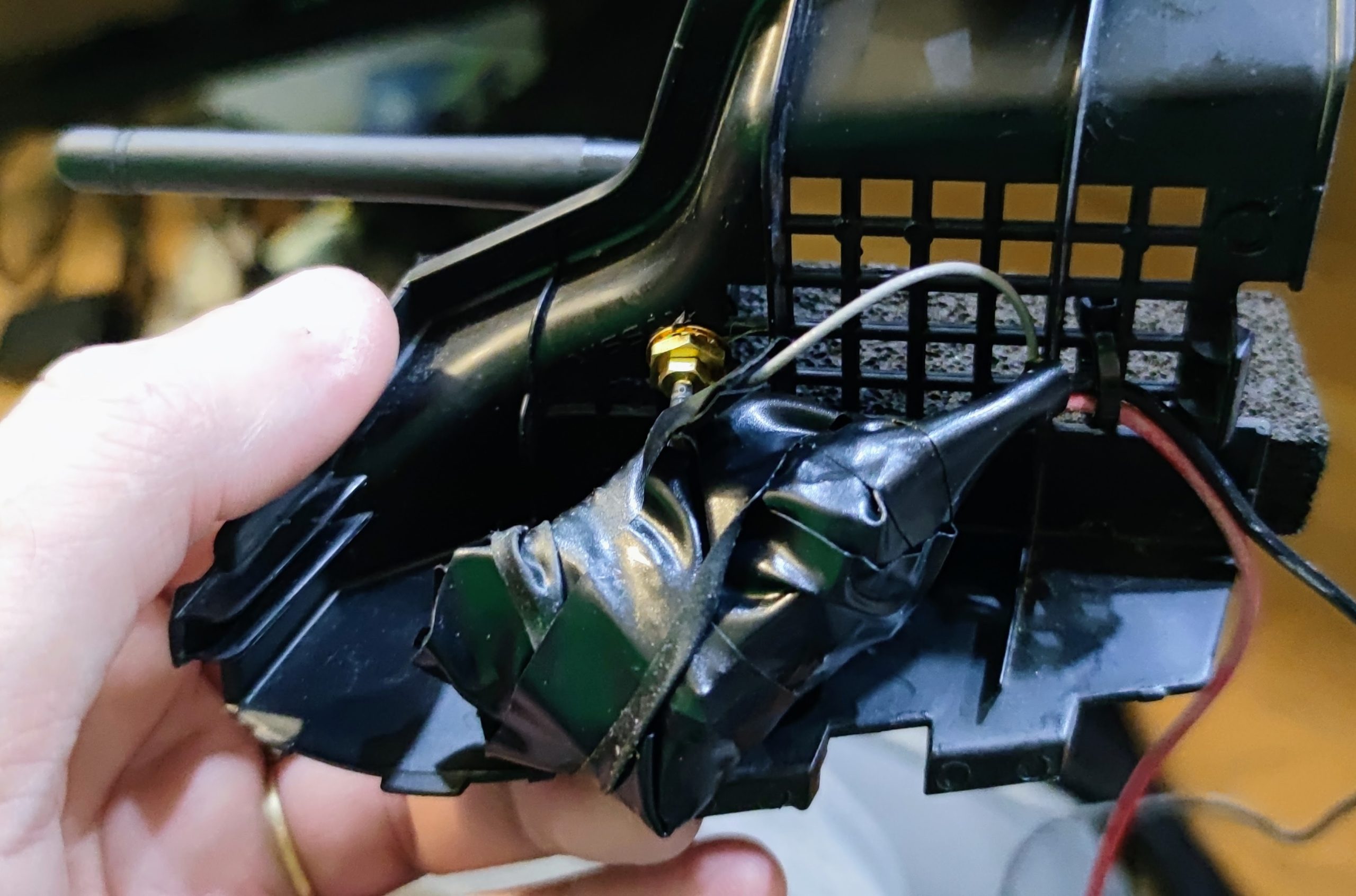
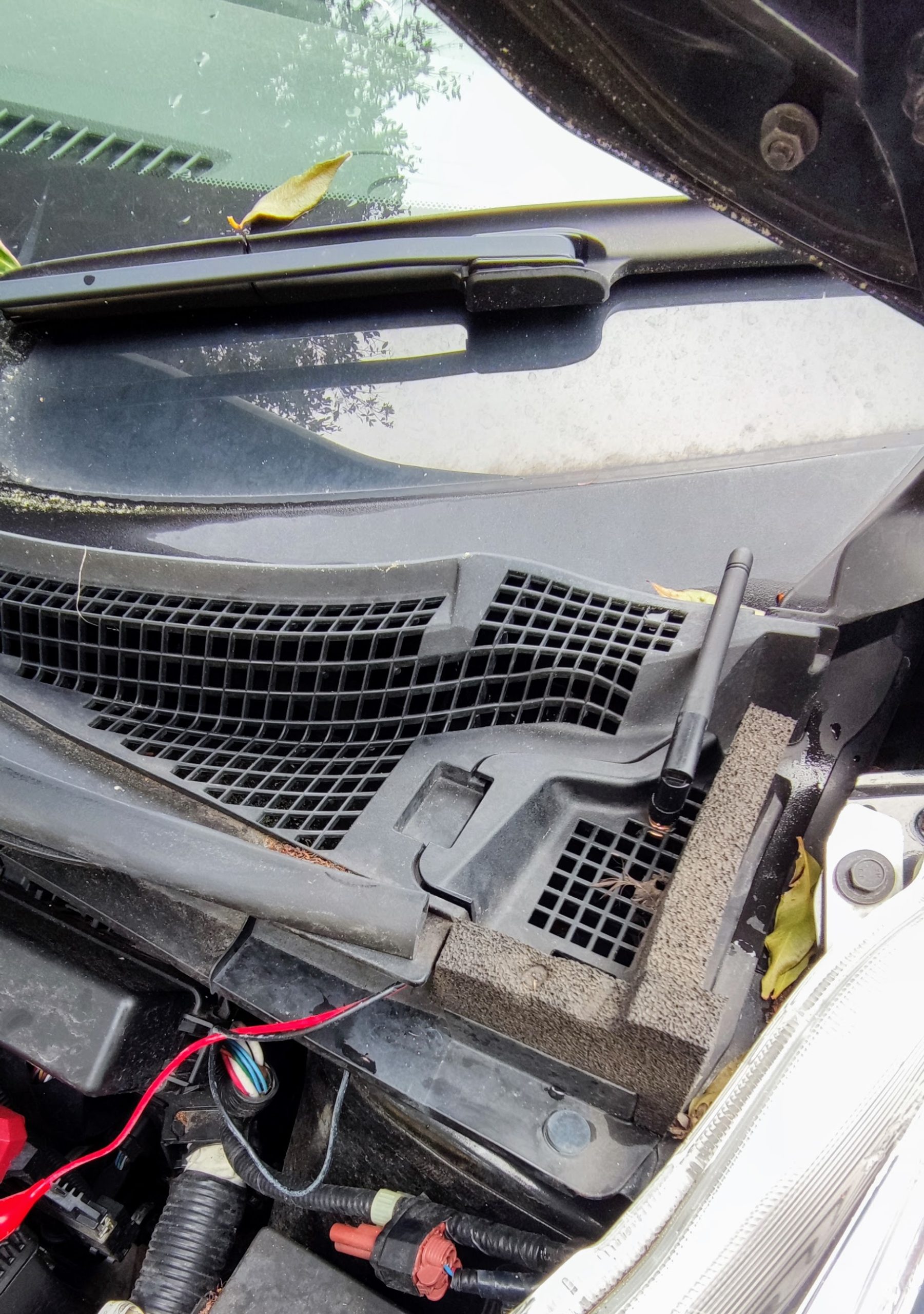

The plastic piece that I mounted the aerial in… and you can just see the tip of the aerial sticking out above the bonnet. (yes I should have cleaned away a few leaves before taking photos)
ESPHome Configuration
There are plenty of places that go over ESPHome setup, but a summary of my configuration is:
- It provides a Voltage value sensor, which I calibrated on the bench with an adjustable power supply, and decent multimeter.
- It provides a ‘Wifi Level’ sensor so I can see if it has good signal.
- it runs for 20 seconds, then deep sleeps for 5 Minutes. This is plenty of time to start up and send values.
- It uses a static IP, so there is no time spend asking for an IP address (quicker to send sensor values)
- It has some linear calibration values (I set these with trial and error on the bench)
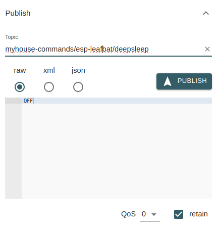
- It allows me to push a value to my MQTT server to turn OFF the sleep mode. Use the retain flag when you publish to give the ESP time to start up and pull these values. This is needed to do updates etc (you need a way to prevent it sleeping!). If you are writing to this topic with something like MQTT Explorer, remember to publish RAW values, not JSON.
In my case I write ON or OFF values to:myhouse-commands/leafbat2/deepsleep
Note that I use a secrets file for the personalized values and the below is the esp-leafbat.yaml file, the rest of which is pretty well commented.
#############################################
#############################################
# Vehicle 12V Battery Monitor
# Monitoring the status of a vehicle 12V battery with
# an esp8266 (D1 Mini).  It will obviously only
# transmit when the vehicle is within wifi range.
# Voltage is measured with a resistor voltage divider
# into the analogue GPIO on the esp8266.
# https://zorruno.com/2022/vehicle-12v-battery-monitoring/
##############################################
#############################################

#############################################
# Variable Substitutions
#############################################
substitutions:
  devicename: "esp-leafbat"
  friendly_name: "Nissan leaf 12V Battery Monitor"
  description_comment: "Leaf 12V Battery Monitor (when home)"
  api_key: !secret esp-bat_api_key #unfortunately you can't use substitutions in secrets names
  ota_pass: !secret esp-leafbat_ota_pass #unfortunately you can't use substitutions in secrets names
  wifi_ssid: !secret wifi_ssid
  wifi_password: !secret wifi_password
  fallback_ap_password: !secret fallback_ap_password

  #Add these if we are giving it a static ip, or remove them in the Wifi section
  #A static IP will speed things up slightly in that it doesn't have to negotiate DHCP
  static_ip_address: !secret esp-leafbat_static_ip
  static_ip_gateway: !secret esp-leafbat_gateway
  static_ip_subnet: !secret esp-leafbat_subnet

  mqtt_server: !secret mqtt_server
  mqtt_username: !secret mqtt_username
  mqtt_password: !secret mqtt_password
  mqtt_topic: "esphome" #main topic for the mqtt server, call it what you like
  mqtt_commandstopic: "myhouse-commands" #main topic for commands (ie sleep), call it what you like

  #web_server_username: !secret web_server_username
  #web_server_password: !secret web_server_password

  update_time: 10s #update time for for general temp sensors etc

#############################################
# ESPHome
#############################################
esphome:
  name: $devicename
  comment: ${description_comment} #appears on the esphome page in HA

#############################################
# ESP Platform and Framework
# https://esphome.io/components/esp8266.html
# https://esphome.io/components/esp32.html
#############################################
esp8266:
  board: d1_mini
  framework:
    version: latest #recommended, latest or dev

#############################################
# ESPHome Logging Enable
# https://esphome.io/components/logger.html
#############################################
logger:
  level: INFO  #INFO Level suggested, or DEBUG for testing
  #baud_rate: 0 #set to 0 for no logging via UART, needed if you are using it for other serial things (eg PZEM)
  #esp8266_store_log_strings_in_flash: false
  #tx_buffer_size: 64

#############################################
# Enable the Home Assistant API
# https://esphome.io/components/api.html
#############################################
api:
  encryption:
    key: ${api_key}

#############################################
# Enable Over the Air Update Capability
# https://esphome.io/components/ota.html?highlight=ota
#############################################
ota:
  - platform: esphome
    password: ${ota_pass}

#############################################
# Safe Mode
# Safe mode will detect boot loops
# https://esphome.io/components/safe_mode
#############################################
safe_mode:

#############################################
# Wifi Settings
# https://esphome.io/components/wifi.html
#
# Power Save mode (can reduce wifi reliability)
# NONE (least power saving, Default for ESP8266)
# LIGHT (Default for ESP32)
# HIGH (most power saving)
#############################################
wifi:
  ssid: ${wifi_ssid}
  password: ${wifi_password}
  #power_save_mode: LIGHT #https://esphome.io/components/wifi.html#wifi-power-save-mode
  manual_ip: #optional static IP address
    static_ip: ${static_ip_address}
    gateway: ${static_ip_gateway}
    subnet: ${static_ip_subnet}
  ap:   #Details for fallback hotspot (captive portal) in case wifi connection fails https://esphome.io/components/wifi.html#access-point-mode
    ssid: ${devicename} fallback AP
    password: ${fallback_ap_password}
    ap_timeout: 30min #Time until it brings up fallback AP. default is 1min

#############################################
# Web Portal for display and monitoring
#############################################
#web_server:
  #port: 80
  #version: 2
  #include_internal: true
  #ota: false
  #auth:
    #username: ${web_server_username}
    #password: ${web_server_password}

#############################################
# MQTT Monitoring
# https://esphome.io/components/mqtt.html?highlight=mqtt
# MUST also have api enabled if you enable MQTT
#############################################
mqtt:
  broker: ${mqtt_server}
  topic_prefix: ${mqtt_topic}/${devicename}
  username: ${mqtt_username}
  password: ${mqtt_password}

  # Availability Topic
  birth_message:
    topic: ${mqtt_topic}/${devicename}/availability
    payload: online
  will_message:
    topic: ${mqtt_topic}/${devicename}/availability
    payload: offline

  # A way to prevent deep sleep using MQTT command
  on_message:
    - topic: ${mqtt_commandstopic}/${devicename}/deepsleep
      payload: 'OFF'
      then:
        - deep_sleep.prevent: deep_sleep_1
    - topic: ${mqtt_commandstopic}/${devicename}/deepsleep
      payload: 'ON'
      then:
        - deep_sleep.enter: deep_sleep_1

########################################
# Deep Sleep
# https://esphome.io/components/deep_sleep.html
########################################
deep_sleep:
  run_duration: 20s
  sleep_duration: 5min
  id: deep_sleep_1

#############################################
#############################################
# MAIN SENSORS
#############################################
#############################################
#############################################
#############################################
# MAIN SENSORS
#############################################
#############################################
sensor:
  #Quality of Wifi in dBm
  - platform: wifi_signal
    name: "WiFi Signal"
    update_interval: ${update_time}
    retain: true #Retain this as you'll have no value between sleeps otherwise
  #Analog sensor for voltage reading (A0)
  - platform: adc
    pin: A0
    name: "Battery Voltage"
    update_interval: ${update_time}
    retain: true #Retain this as you'll have no value between sleeps otherwise
    filters:
      - multiply: 3.3 #D1 mini V divider, 3.3V -> 1V on esp8266
      - calibrate_linear: #Read values with voltmeter and bench supply
         - 3.11 -> 14.00
         - 3.00 -> 13.50
         - 2.89 -> 13.00
         - 2.77 -> 12.50
         - 2.67 -> 12.00
         - 2.55 -> 11.50
         - 2.45 -> 11.00
         - 2.34 -> 10.50
         - 2.22 -> 10.00
         - 2.11 -> 09.50
         - 2.00 -> 09.00
Graphed Results (Influxdb and Grafana)
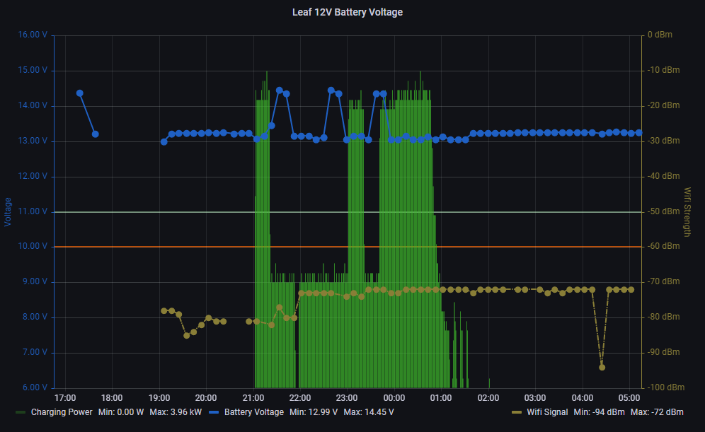
This is a graph showing charging power (in green, in Watts), which I was already monitoring elsewhere plus the overlay of 12V battery voltage and Wifi Strength from ESPHome.
There are sometimes the odd gap in the 10min cycle (eg Wifi Strength missed) and large gaps are when the car is away from home. This graph is since I have put a Lithium 12V battery in place, which should be fully charged to about 13.2V.
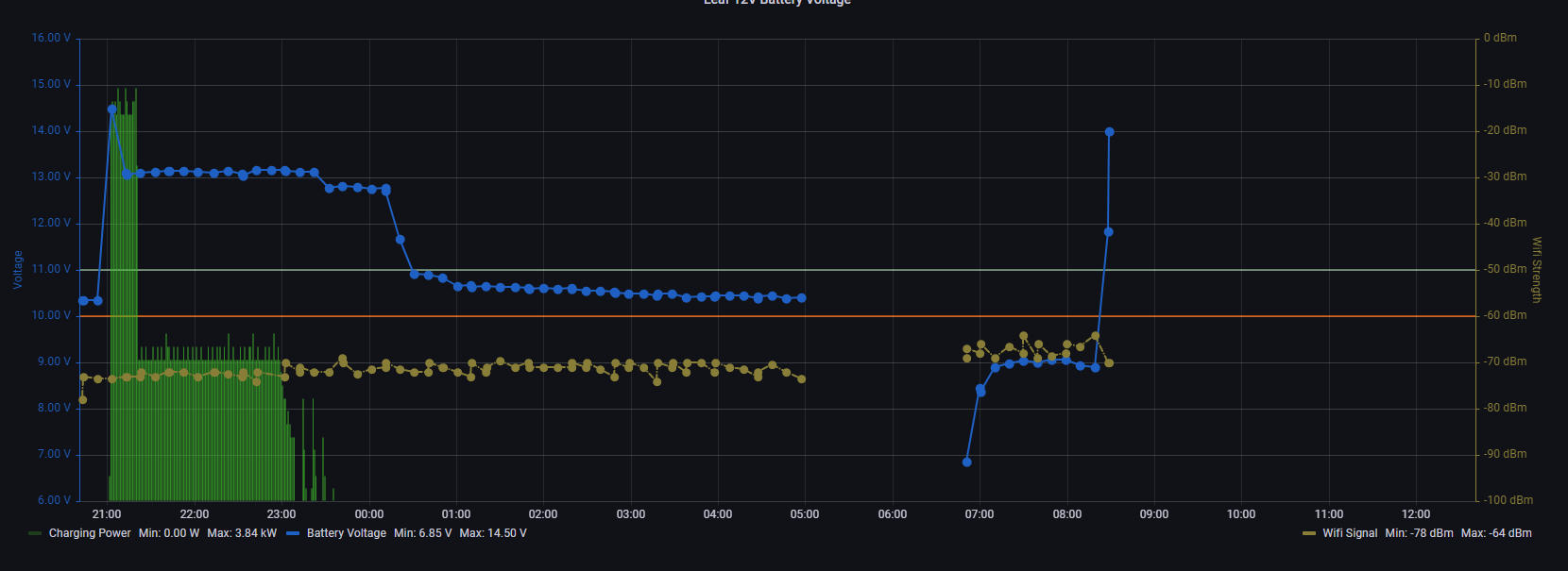
Below is the sort of measurement I was getting with the lead acid battery, before I replaced it. Interestingly, the car would ‘mostly’ start and drive when the battery was hovering around 10.5V. Occasionally it wouldn’t though, requiring us to carry around a lithium jump pack. Even with the traction battery charging, there wouldn’t be enough to get the 12V up to spec (it was pretty stuffed by this stage)
The car also did some weird things with a low 12V battery, including brake issues on startup… sometimes you’d start the car and put your foot on the brake and there would be none! Obviously the brake booster needed a but more Voltage to perform. After a few seconds it would kick back in.
The rapid rise again at just before 7am was when it was put on a mains fast charger.
Using this for vehicle ‘at home’ notification
I did have my Home Automation setup letting me know whether the vehicle was home or not by way of checking WiFi connectivity. The main reason I used this was to remind me if the car was home, and I’d forgotten to plug it in. No power drawn from the charger, at the planned charging time….? Notify me, but ONLY if the car is home. This is not a bad way to do it, but I have also been playing with bluetooth iBeacons, so thought I’d put one in the car.
I experimented with ESPresense a while back, but have recently (July 2024) installed Bermuda on Home Assistant to do trilateration of bluetooth devices. I had put some battery iBeacons in my cars, but embarrassingly in one vehicle, the battery has run out and I have no clue where I put it…! So, on a recent rebuild of one of my battery monitors, I put a cheap iBeacon in, with no case, the CR2477 battery holder removed and connected to the 3.3V of the D1 Mini. See the pic below, but note I then covered it in wide heatshrink and self-amalgamating tape for waterproofing.
Improvement ideas (yet) to be done
- Measure current in and out of the battery.
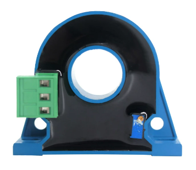
I have bought a range of current measuring sensors, and something like the hall effect CT is what I’ll be using. 100A range would likely do, and it gives 0-10V out. I ordered a few options to play with.
Using an ESP8266 is a bit of a pain for trying to do this as it only has one Analog input though. An esp32 would probably be a better idea, or maybe an i2c adaptor. It would be great to see just how much current is flowing in and out when driving and charging. - Have a method of complete/automatic disconnection
For our cars with no large traction batteries (ie non-electric) would be nice to have the device disconnect itself completely if the voltage was too low. Probably not really necessary as it draws very little in sleep mode at <10mA, but it could be done by having the device switch on with the car ACC circuit) and latch until the voltage dropped below a set level. Mosfet control probably best, but it would need +ve switching. This could mean that other devices, such as Dashcams could be connected to this same Mosfet… ah la instant low voltage accessory switch. - Measure 24/7 when the car is not at home
Having SD storage and logging to that would be a good idea. It would be nice to be able to push historic data to influx DB (haven’t investigated this… and not sure whether time series databases like this idea). Doing this would mean going away from something simple like core ESPHome though… but there have been a couple of feature requests and discussions about having ESPHome log to SD.
It might be nice to see if the car can keep up with charging the 12V battery when other systems are on.


Great job. Love your documentation,
Thanks Doug
Thanks, great project!
I’d like to build one for my Kia Soul EV (same brake issues) and probably even for my lawnmower tractor
Hi,
I would like to build this myself. Which hall effect CT did you use? Do you have a link?
Cheers
to be honest, I haven’t got around to implementing current monitoring. I did get a couple of CTs to play with though… just need to ensure they have enough current range and are for DC. e.g the WCS1500 (example: https://www.aliexpress.com/item/32898633287.html ) or these ones have split cores and do 0-5V https://www.aliexpress.com/item/1005006414264915.html
Hi Zorruno,
I have built one using a D1 mini with 1220k ohm and 100k ohm to measure the car battery. The data is sent to HA API at home. It works perfectly with the deep sleep. However, I am facing a problem when I drive my car to another place not within the intranet, the esphome node would continuously search the WIFI and not going to deepsleep. Do you have such kind of problem? Thanks
hmm, I don’t think mine does that sorry – it goes into deep sleep without fail as far as I’m aware. If it can’t find a recognised Wifi AP it still sleeps – I have tested it using my phone’s hotspot.
Thanks so much for the write-up.
I’ve created a version of this with a 33k and 8.2k resistors which should give an output voltage of 3.3v from the 16.5v input but I seem to be getting a reading of 1v regardless of the input. I’ve only managed to test it with a 12v battery jump pack and a 9v battery so far but I would expect some difference in the reading. From using the calculator 9v should be 1.79v and 12v should be 2.39v. However, the Wemos D1 Mini Pro has an internal voltage divider and I’m not sure if that needs to be part of the calculation.
Currently I am returning the unfiltered ADC result and it’s always 1.0.
Hi, no problem, glad it was useful so far. Firstly, just note that a recent change meant I stuffed up the deep sleep YAML… so I’ve updated it. Secondly you shouldn’t have to worry too much the exact voltages (or resistor values), as you really need to calibrate it anyway. You can use “multiply: 3.3” under filters to get closer to the actual voltages to the A0 for the D1 Mini (I haven’t in my YAML), but again, it doesn’t really matter as you use the calibration values (and test with a decent voltmeter/multimeter) to get the output numbers you want. Sounds like you have something else going on there… maybe borrow a cheap bench top supply you can ramp up and down to test? You’re not using the USB port for power as well as another supply are you (multiple power supplies might cause issues, unless grounds are connected)? Maybe try another D1 Mini?
It turns out I’d wired my resistors incorrectly. I had four legs as I built it a little too literally, so I had VCC, GND, A0 and another GND which I grounded to the ESP and that seemed to cause issues.
I’ve redone the resistor with 3 legs, VCC, GND and A0 and I’m now seeing more realistic numbers, just need to calibrate now.
I spotted the deep sleep issue and fixed it in my code 😉
nice spotting. BTW, if you get the sleep code wrong like I did, it is not fun when it goes to sleep for ever 🙂 I just had an esp8266 board fail on me on another vehicle monitor, so it is handy that I could just disconnect it, replace the D1 Mini and upload the replacement YAML via USB. (Note also I did add the 3.3x multiplier in my YAML, and put it in my notes above)
The biggest issue I have right now is that the jumper wire which is needed to enable deep sleep mode seems to disable USB flashing.
Is the jumper on D0 (GPIO16) to Reset (RST)? This shouldn’t affect programming, unless maybe there is code telling D0 to pull low. If all wiring is on a daughterboard (eg D1 Mini power shield) then you can pop it off and program without it anyway.
Nice project! I plan to put it into an OBDII enclosure. As I see, it would be simpler to add a single 1.3M resistor to achieve the desired voltage division: as the d1 already has a voltage divider (r1=220k, r2=100k), it will increase r1 to 1.52M. This way the max voltage would be 16.2V, and there will be less components / solders.