Tasmota Flash of GLD110HA Smart Globe
Summary
Flashing a cheap Wifi connected smart light bulb with Tasmota (attempting to use Tuya Convert method, but reverting to a hardware flash)
Product Summary
Note as at 2022 these devices are likely using a WB3L chip or similar that is not an ESP8266 device. You can identity these by looking at the printed label on the bulb itself, where it will clearly be labelled as Series II. The original variant which is ESP2866 based, will not identify as Series I. See my notes on replacing the chip with an ESP12F.
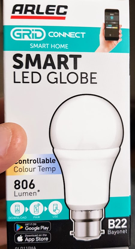
- Arlec Grid Connect Smart Home LED Globe
- 806 Lumen, White only, but controllable colour temp (between 3000k, 5700k)
- This is the B22 Bayonet version of E27 (Edison screw) model GLD112HA
- There are GLD120HA (B22) and GLD122HA (E27) models which are also RGB and also some E14 versions.
- Bought from Bunning NZ, September 2020
- https://www.bunnings.co.nz/arlec-grid-connect-smart-9w-806lm-rgb-cct-bc-globe_p0111500
- NZ$22 at time of purchase (RGB versions were around $25)
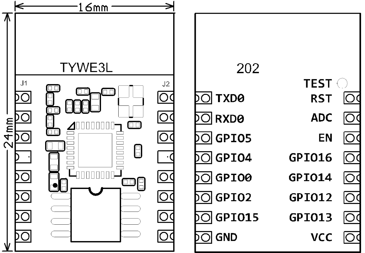
- Contains TYWE3L Chip
https://developer.tuya.com/en/docs/iot/device-development/module/wifi-module/wifie3lpinmodule
Tuya-Convert Method not working

As at Sep 2020, the tuya-convert method doesn’t work on the iteration of the model I had. When set to flash, the bulb would recognise something happening and come out of setup mode… but tuya-convert would time out. Likely related to this:
https://github.com/ct-Open-Source/tuya-convert/issues/483
https://github.com/ct-Open-Source/tuya-convert/wiki/Collaboration-document-for-PSK-Identity-02
Hardware flash
Disassembly
- The opaque cover can be prised off with a screwdriver. There is a bunch of silicon or rubber glue holding it in place.
- The LED board just pulls off (once a fair bit of that silicon is scraped off). It has a pin socket connector that is slipped over a plug on the main board.
- You prise out the base bulb pins which are a compression fit and they hold the 230V tails in place. The the main board just pulls out.
Flashing with Tasmota
- Unfortunately the TYWE3L board has 2mm pitch, and I don’t have a nice pogo pin clamp at 2mm pitch currently so soldering was necessary. It was easy enough to get some wires soldered on though.
- TX/RX, 3.3V, GND and GPIO0 are all easily accessible on the TYWE3L edge and flashing with tasmotizer (or similar) and an FTDI was relatively straightforward. I backed up the original firmware (although there was little point), and the first flash timed out for some reason but the second was fine (Flashing the full tasmota.bin binary was fine)
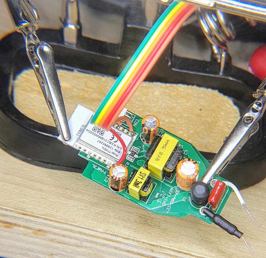
- In my photos you can see I have GPIO connected with an orange wire and it is then attached to a grey flying lead with a pin – to flash, I just hold this pin on GND on power up (The orange wire isn’t connected to the FTDI adaptor in case the photo looks confusing)
- The “FTDI serial Adaptor” seen in the photos is a useful too that comes from Johnathan Oxer at https://www.superhouse.tv/ . The button and connections on it help mainly with connecting to and flashing sonoffs, but also useful for other devices.
Reassembly
- Putting it all back together later, you just need to align the mains tails though the holes then press the pins back in place which clamps the tails.
- The cover could probably do with some more silicon to keep it in place but it clips back together loosely.
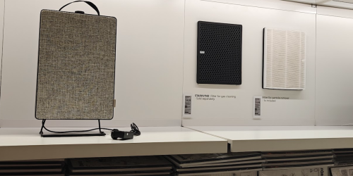
Photos of the unit and flashing etc
Links & References
- https://esphome-configs.io/devices/arlec-grid-connect-smart-led-globe-rgb/
- Equiv from Aliexpress https://www.aliexpress.com/item/33006613923.html
- https://www.reddit.com/r/tasmota/comments/gph67n/arlec_smart_led_globe/
- https://templates.blakadder.com/arlec_GLD112HA.html
Original Firmware Backup
Stored here for posterity
Commands for getting an AP up to sniff the original traffic
Used an old Netcomm NP545 wifi usb adaptor (the laptop wifi would not support AP mode)
git clone https://github.com/oblique/create_ap
cd create_ap
sudo make install
cd ..

sudo create_ap --no-virt wlx006064368445 eno1 AccessPoint pass1234

tcpdump -i eno1 -w capture.pcap