Whole House 3 Phase Power with PZEM-004T
Purpose
A robust, accurate, low cost and safe whole house electricity monitoring setup, using PZEM-004T modules. These use current transformers (CTs), and send data as TTL Modbus-RTU. Recently Tasmota has added support for up to 3 of these directly (on the same data channel) so there are fewer hoops to jump though to get them working (previously my testing involved sending serial commands)
Project Goals

The project evolved into a small companion switchboard and combined a few additional needs. I’ve split the article into the 3 parts
- Switchboard case, and the use of 3 PZEM-004T modules to measure ALL incoming power (and at maximum accuracy) including fluctuations in voltage and power factor (This article)
- Main (and companion) switchboard temperature monitoring (could be useful)
- Switchboard open/close detection (why not)
- Measure other energy sources using kWh meters with impulse outputs (EV Charging, and a remote sub DB)
- Whole house 3 Phase surge suppression/protection (just because I could)
This page is not a full project build, but my notes for the main parts and how/why it was put together
Equipment (For all parts of the project)
3x PZEM-004T (eg, Aliexpress, various suppliers) In plastic case, with CT
2x Pulse count kWH Meters. (Bought locally for SDoc compliance, but there are many imported versions). The ones I got were 100A and 1 pulse per 2Wh.
1x Wemos D1 mini (eg Aliexpress)
1x Hi-Link HLK-5M05 (or other 5v power regulator of about 0.5 of an Amp) (eg Aliexpress)
1x 4 Pole Surge Suppression module rail mount (eg Aliexpress)
1x perf or veroboard to mount everything on (from Parts box)
1x 2 row, 12 way switchboard case, with rails etc (I got locally from a supplier for around NZ$42)
1x 3 Phase MCB/Main switch (I already had a Schneider 20A unit, unusual model but perfect for this job)
3x MCBs (I already had some GE quality 16A ones spare)
2x DHT11 temp/humidity sensors
3x BAT38 or equiv Schottky diodes
Shielded data cable for current transformer extensions etc
Board mount 1A fuse, 5mm LED, Resistors 1k (3.3v pullups), 10k (serial pullup), Wire, connectors etc
1x 300 Ohm (approx) resistor for LED
Plastic cover insert for DB (to stop fingers entering the DB top row)
PZEM-004T Individual Setup and Summary
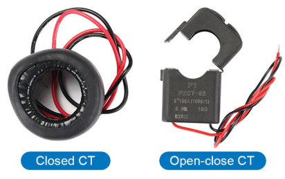

These modules should be bought with a current transformer coil, and they are the Version 3, 100A units.
You can buy them with a split coil if you can’t or don’t have someone competent/qualified to remove the incoming mains wiring. I also completely recommend buying them with the plastic case (clear blue so you can still see the internal LEDs etc) for safety reasons. They have optical isolation across the board, but no protection for fingers etc.

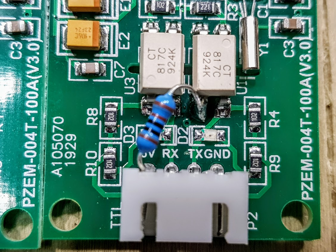
The serial output is TTL level, and we will be needing around a 3V signal into our Wemos so they need a 1k Ohm resistor mod internally.
Notes on resistor mod: https://tasmota.github.io/docs/PZEM-0XX/
Using 3x PZEM-004T with serial comms
The modules use Modbus-RTU and can have an individual ID set for serial replies. Tasmota added support in late 2019 for up to 3 PZEM modules on the same bus (hardware or software serial is fine)… and no you can’t run more than 3 at this stage due to memory and performance limitations.
Multidrop Wiring

To avoid clashes on response, some diodes need to be added when more than one are used, the circuit also needs to be pulled high and below is a wiring diagram. A fast/low voltage drop Schottky diode is really needed to make the comms work successfully. Remember to cross over RX/TX from the Wemos to the PZEM modules.
Setting Module ID
As well as wiring for multidrop, the devices need to have an ID set (Sometimes referred to as IP address online, but it is a serial address). Tasmota now also allows you to set this easily with the ModuleAddress command – previously this was done with some serial commands (or with windows software linked below, but I tried this unsuccessfully).
To set the address, connect each module one at a time and on the Tasmota console, run (eg)
ModuleAddress 2You’ll get a response to say ‘Done’, but there is no reply to ensure it is carried out successfully. Obviously, set 1, 2 or 3 as needed but remember to disconnect the others when you set each one.
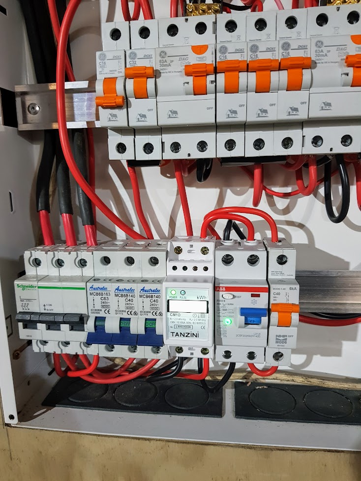
Main DB CT Connections

A photo of the connected CTs in the main DB is to the right. The leads were extended (using shielded data cable that was grounded at the main DB end – likely not necessary, but it was what I had anyway).
You can see the green earth cables running to the earth bus at the top of the board. Again, probably not necessary, but I earth everything I can, for safety and interference purposes.
Tasmota Configuration
This is not a full detail on Tasmota setup, but some notes for this project. There are plenty of places to learn about installing and configuring Tasmota on a Wemos D1 Mini

- I chose “Generic” Module type for the Wemos D1
- I used hardware serial, and therefore TX GPIO1 (Serial Out) is selected as PZEM0XX Tx (62)
- Important Note: RX GPIO3 (Serial In) is PZEM016 Rx (98) (NOT: PZEM004 Rx (63))
- A screenshot of the Generic Tasmota Module Config (Before I added all sensors I finished up with) is to the far right.
- A screenshot of the of what the Tasmota web display looks like with sensors active.
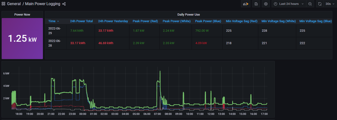
A graph of power for the 3 phases is above (over 24 hours) plus some summaries. You can see large fridge/freezer cycling on and off on the white phase.
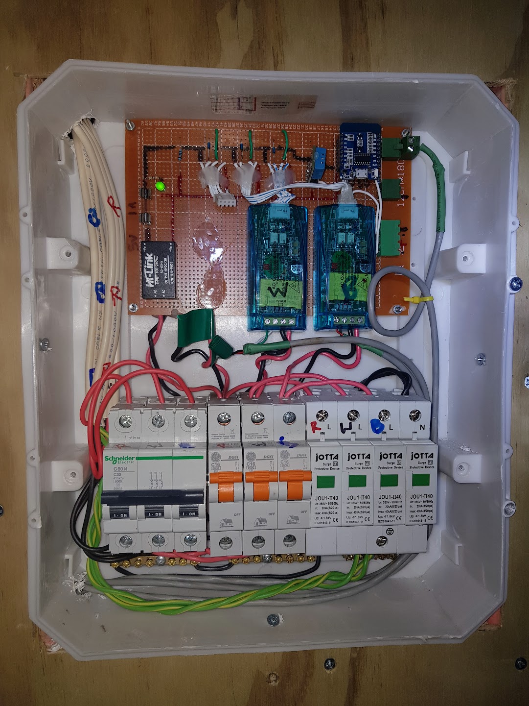
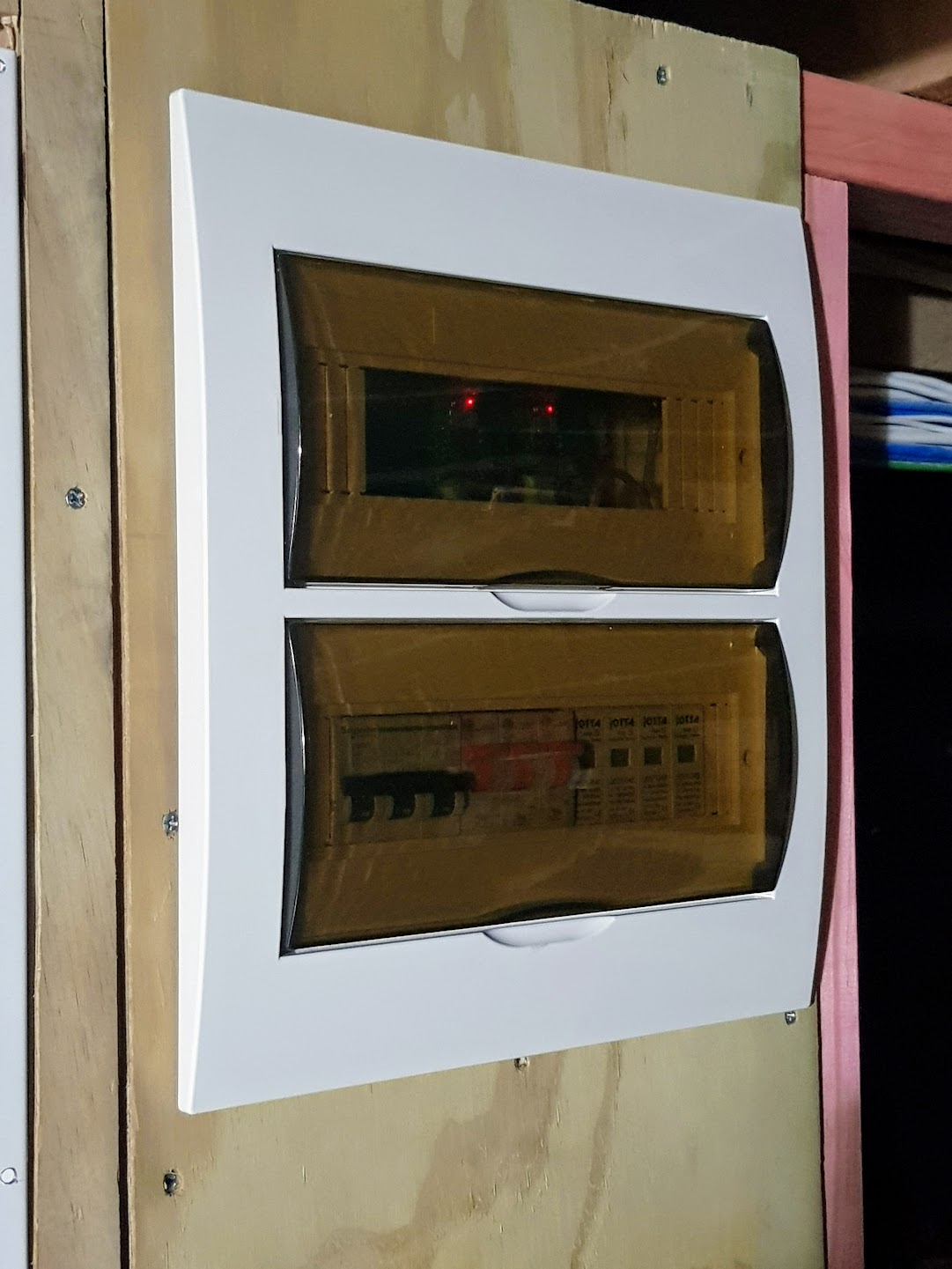
Final Board Layout and Pics

Improvements and Safety Notes
Obviously, note that you must understand the licensing requirements for your country if carrying out any electrical works
- The whole setup was designed to be completely separate to the main DB so it could be disconnected or removed in future easily if ever needed. It would be a lot simpler (but less safe) to just install all of this in a main DB.
- It was very handy having a way to easily power the board without having 230V connected (I bought out the 5V to a connector on the right hand side of the board)
- I took care to separate the 230V from the low voltage by dremelling away some of the perf board tracks where the 230V was connected under the Hi-Link HLK-5M05
- I used individually twisted/shielded cable to feed the coils (and grounded the shield at the main DB end) for a couple of reasons. I was concerned there may be slight interference with extending the coil tails, and also wanted to ensure that the cables were more protected from damage. I also had some nice robust data cable perfect for the job, and extending the CT leads more than 30cms or so is probably not recommended.
- I suggest you buy a spare set of surge suppressors, in case one blows and you want to replace it quickly. It would be nice to have a monitoring circuit to notify on suppressor failure, and although it looks like the surge base has the possibility of switching something, I haven’t seen anything sensible to do this yet.
- Care is needed to understand the neutral & grounding methods for our MEN systems. For convenience separate neutrals were run direct from the main board (but bonded them in the sub board anyway), but the earths can’t be bonded to the Neutral in the sub board.
- If you or your electrician doesn’t understand the electrical connections, don’t do it. You need to wire each phase to each correct PZEM, to get sensible phase, Voltage and power comparisons. If you run them off one phase, you also won’t get sensible results. You also have to understand any RCD/RCBO circuitry in the main panel to ensure any earth leakage detection works correctly.
- Research suggests it is a good idea to short out the CTs if you set them up and don’t connect them to the PZEMs, as high current flowing though can damage them if open circuit.
- I also put a simple glass fuse on the 5V rail (I used 1A), and an LED to see if the fuse was intact.
Additional Links & Info
Tasmota PZEM Summary Page: https://tasmota.github.io/docs/PZEM-0XX/
PZEM 3 Phase Wiring: https://github.com/arendst/Tasmota/issues/2315#issuecomment-384643624
Setting PZEM Device IDs via serial commands: https://github.com/arendst/Tasmota/issues/2315#issuecomment-527894673
Windows Software for the PZEMs (on my G Drive, no promises it won’t contain spyware from the supplier): https://drive.google.com/file/d/1UFmQ8QEyVJhMIQZzhti2v0CutlplsEqz/view?usp=sharing
Note, this was touted as a simple way to set the device ID, but I couldn’t get it to work – potentially as it may need the 230V connected to do so. (confirmed as working with mains connected by Bogdan from Slovenia)
Another ESP8266 project using PZEM-004T these with 3 phase: https://github.com/apreb/eNode