Home Automation of Rinnai Gas Heater
Changes
2021-07-27 V1 – Started Documenting
2024-07-24 V2 – Minor updates, move from old wiki site to this one, added photo album
Summary
Connecting to a Rinnai Neo Wall gas heater for home automation control.
WARNING: I’m controlling a gas fire here, and know what I’m doing. I’m not modifying the unit at all, but just emulating button presses. All the modifications are easily reversible and no safety features or normal control operations have been removed.
Goals
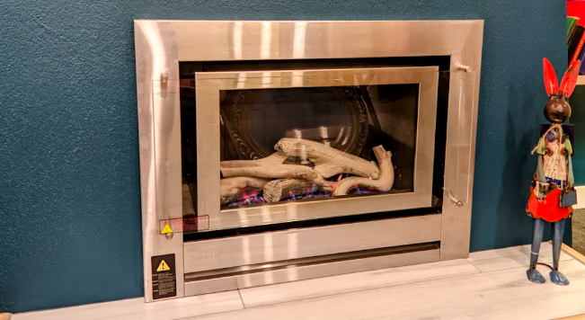
Our Rinnai heater is a wall mounted/flued gas fire. Current control is via a large proprietary LCD remote control that also acts as the temperature sensor, and thermostat. It has some auto timing capability via way of programming the remote, but it is a bit clunky and not intuitive.
The goal was to firstly enable basic on off functionality from my home automation system (home assistant/node red) and in future enable a better PID control of the temperature. Initially, the setup should just allow switch off/on control (for occupancy, remotely before arrival, voice control, better scheduling etc).
These notes don’t show the future temperature automation piece, or other on off automation, but show how I connected to the heater and enabled control via Home Assistant.
Investigation
Initially I played with using SDR to interrogate the remote control (and a 433MHz learning remote) to see if I could replicate the signals. The remote unfortunately doesn’t really have ‘on/off’ and temperature settings, it is more designed around the thermostat functions built in.
For reliability, I decided to take the front off the unit and review this and the circuit diagrams I could find (block schematics only) to see if I could control it with an arduino or similar. It is more sophisticated than I first though, which was good and bad… bad that I couldn’t just ‘wire a remote switch to the burner control’, but good in that I couldn’t really cause any safety issues. All the safety controls such as overtemp, fan speed, starter timeout etc were managed by the Rinnai controller and will remain that way.
I wanted a completely non interfering system… if I removed the controls or they failed, all other functionality (including the remote) would work fine.
I found there were push button controls on the front that were wired to a control board via an 8 core network cable. Once I had removed and traced this simple board, I found that I’d be able to monitor 2 LEDs, and 3 buttons, The buttons were on/off, and flame up, flame down. I would know the state of the unit via the LEDs. The bonus later was that I found 5V that proved enough to supply an esp8266 board and some relays.

Switch Plate Layout
looking at the board, shows this:

Solution
I used an esp8266 board (a Sonoff DEV board as that is what I had spare with an adequate number of i/o) and a separate 5V, quad relay board. I had hoped to get away with using 2 relays, and directly connect one of the i/o pins to pull the switch low for on/off, but it ended up that internal pullup resistance meant that the input for temp down was always seen.
I used the tried and stable Tasmota that I was familiar with rather than flashing something custom. This is pretty easy to get working as a device that just monitors i/o and pushes results to MQTT.
Tasmota Setup
- Set to ‘generic module‘ (I actually changed to the sonoff DEV which is what I was using, but there is little difference, except for more I/O being displayed on the generic template)
- Set i/o for relays as relay_i 1, 2 and 3. (Inverted relay was necessary as I am driving them with +ve 5V for on)
- Set i/o for monitoring LEDs as switch 1 and switch 2
- Set switchmode1 to 2 (this gives an “on” for LED on and “off” status off with LED changes. Default is “Toggle”)
- Set switchmode2 to 2 as above for the other LED input
- Set setoption114 to 1 to decouple the switches from the Relays (by default, pressing a switch in tasmota will activate the associated relay. We don’t want this)
- We are wanting to operate the relays for a short period only, to mimic a button press. This could be done in automation, but doing it in Tasmota ensures we don’t latch anything on. Use the command PulseTime for this, and a value of 2 gives 2 10ths of a second, which is adequate.
Much of this can be done in the web gui, but the console commands are:
module 18
gpio4 switch 1
gpio5 switch 2
gpio12 relay_i 1
gpio13 relay_i 2
gpio14 relay_i 3
switchmode1 2
switchmode2 2
setoption114 1
pulsetime1 2
pulsetime2 2
pulsetime3 3
you can check the values of pulsetime by just using the command “pulsetime” without a value. Mine gives this answer in the console:
stat/tasmo-sdev-8126-gasheater/RESULT = {"PulseTime1":{"Set":2,"Remaining":0},"PulseTime2":{"Set":2,"Remaining":0},"PulseTime3":{"Set":2,"Remaining":0},"PulseTime4":{"Set":0,"Remaining":0},"PulseTime5":{"Set":0,"Remaining":0},"PulseTime6":{"Set":0,"Remaining":0},"PulseTime7":{"Set":0,"Remaining":0},"PulseTime8":{"Set":0,"Remaining":0}}
Completed controls (on initial connection)
Connecting to the tasmota device gave me the ability to read if the heater was ON, OFF, or on STANDBY. I could turn it on and off, and if it was turned on by pressing the heater button, Home Assistant would know.
This is necessary for good home automation in my view, as this means it can operate as normal.
Straight away, I can turn the heater on and off via automation and ensure it is off (very important) and later I can carry out some controls to ramp the manual control up and down to the set flame levels.
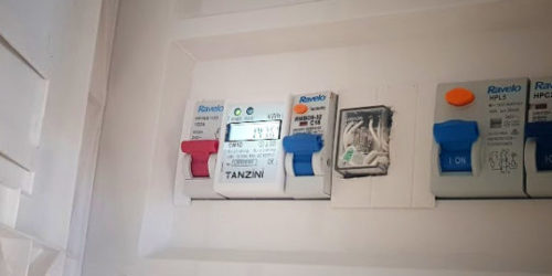
The switch board was nicely connected with an RJ45 Jack, so I could just parallel up a jack (see the photo below of the yellow splitter I used) to the new controller. I can remove this at any time for 100% normal operation (another mandatory automation requirement for me, for any major piece of equipment I’m controlling)
Product Manuals
Rinnai Neo User Manual
https://drive.google.com/file/d/0Bw25VX4SfMVGVTNURWJYU0piWjg/view?usp=sharing
Rinnai Neo Install Manual
https://drive.google.com/file/d/1HYjPEGPggSgHRz2T6CE0eK3NtVCrYdJD/view?usp=sharing
Resistors
S1 is Standby – 0 Ohms
S2 is Up – 24k (15k + 6.8k + 2.4k)
S3 is Down – 39k + 24k
Photos
Various photos of the board, connections and box including some of the Rinnai internals are shown below